|
|
Click the  next to the title to expand that section.
 Introduction Introduction |
||
|
|
| Field Installation |
|
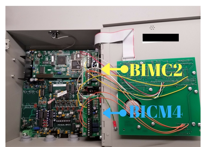
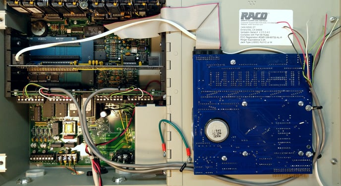
The BICM modules are normally installed at RACO but may be installed in the field if necessary. This requires proficiency at soldering to PCBs. There are many permutations depending on the BICM type, the RTU configuration, and how many modules are installed but the basic process is the same. All that varies is the physical mounting and the exact locations where the wires are soldered.
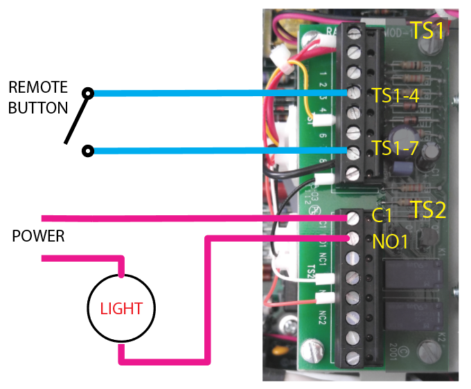
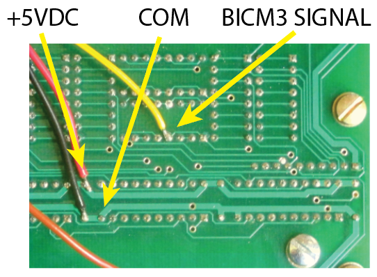
The BICM is wired to the Front Panel Display PCB which is mounted to the door. It requires connections for:
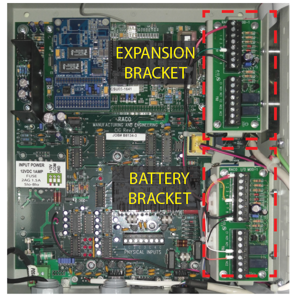
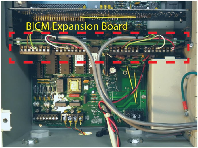
A. Mounting the BICM module The BICM modules are mounted in one of three locations: On the battery bracket, on a bracket that is bolted to the RTU’s case, or on a card that goes into an empty expansion slot. The location is not critical as long as there’s no physical interference. The card-mounted modules can go in any empty slot where there’s space. The card is just for mechanical mounting and is not electrically connected to the RTU. Coordinate with RACO to determine the best location for your RTU. B. Wiring the BICM module Observe standard electrical safety and ESD precautions when handling or working on the RTU and BICM modules. Follow all local and site specific electrical codes and procedures.
C. Testing the BICM module
|
| Mounting Options |
|
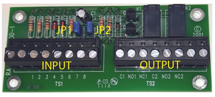
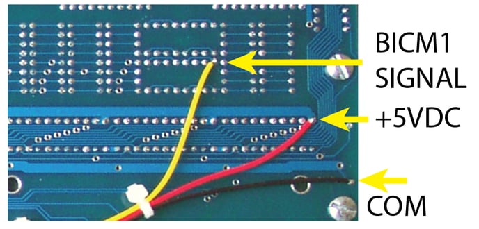
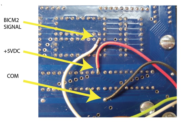
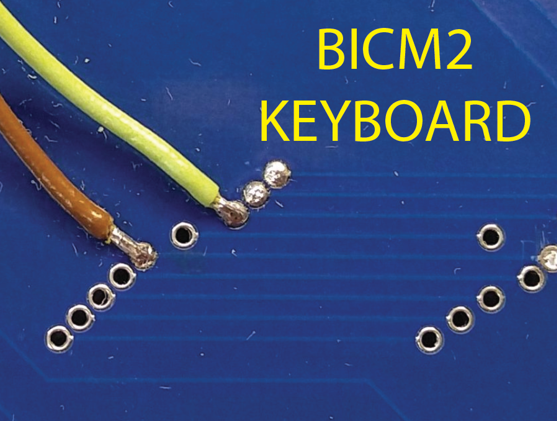
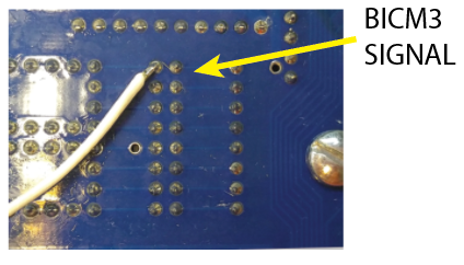
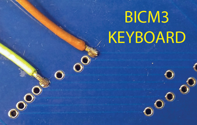
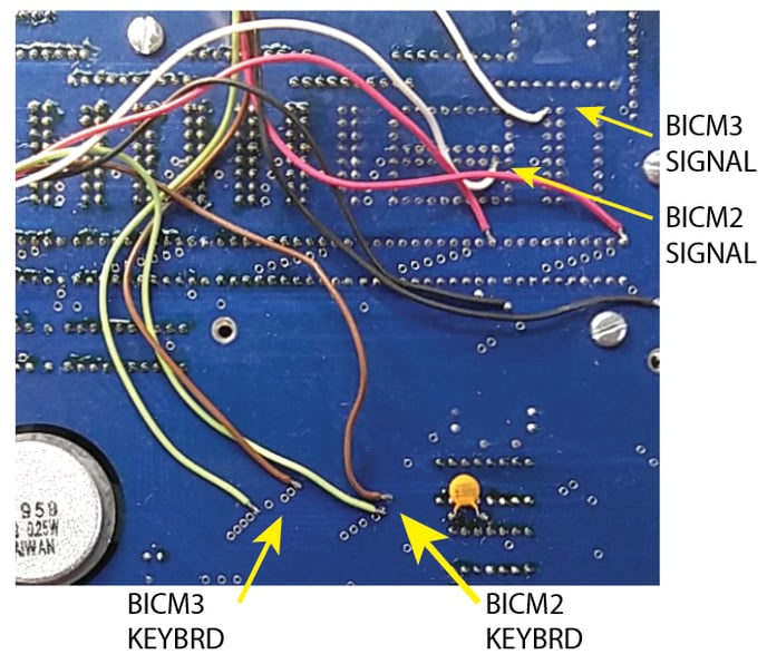
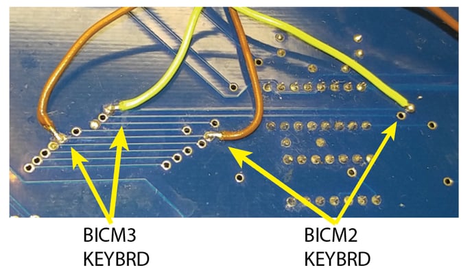
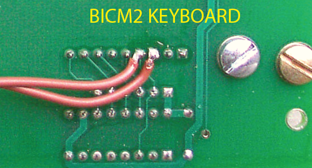
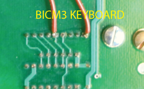
Wiring & Schematics Verbatim Internal Wiring Note: Wire colors may vary depending on the manufacture data and configuration. The keyboard wires (Brown and Green in these pics) are not polarity sensitive and may be connected either way.
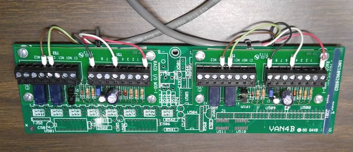
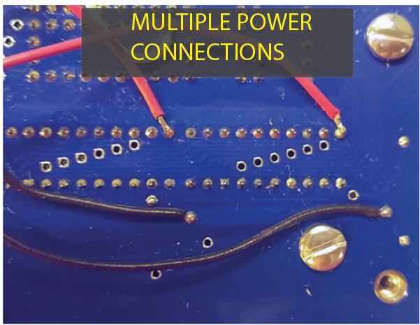
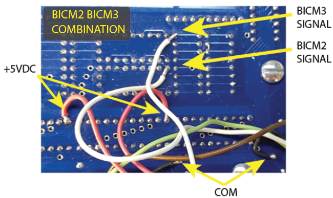
When installing more than one modules, there will be instances where two wires may need to go to a single connection point. One of the wires will need to be soldered to a different point in the same PCB trace.
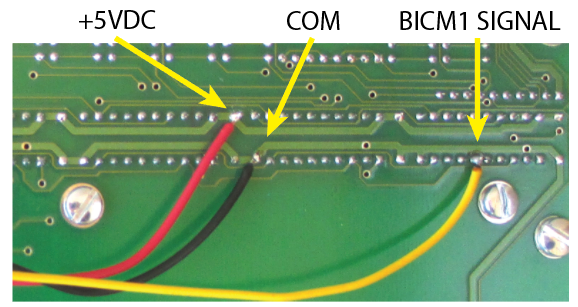
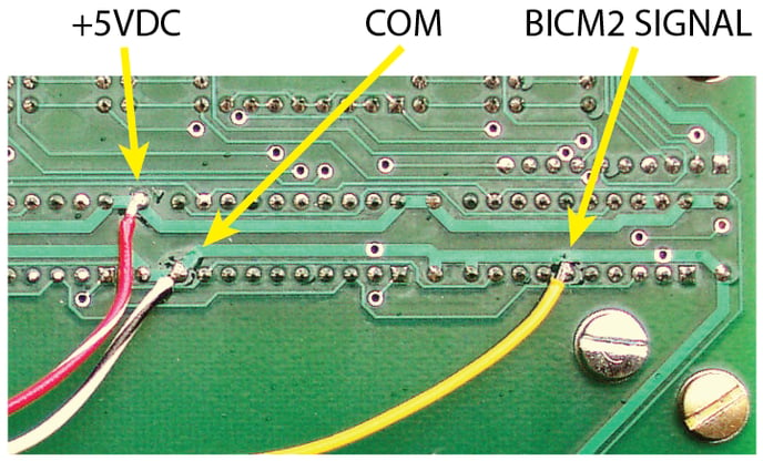
Catalyst Internal Wiring
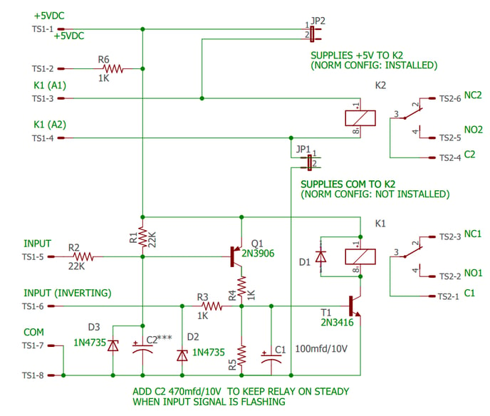
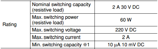
BICM Schematic
|
-jpg.jpeg)