The information provided in this document helps the user setup and test the Catalyst Ethernet Module. The main purpose of connecting to the Ethernet network is to access the PLC data natively instead of connecting on other external network bridges.
This addendum is in effect a new section to the Industrial Networks section of the Catalyst Owner's Manual. Therefore, the content of this addendum covers all the requirements of connecting to the Ethernet network, which also includes all testing and diagnostics.
Prior to starting this process, please ensure:
- The user is familiar with the basic operation and programming method of the Catalyst product and the Ethernet-specific software. Only the Ethernet-specific features of the Catalyst are described in this addendum.
- The Catalyst is setup and functioning in accordance with the manual.
- The user has basic familiarity with Windows PCs and networking.
- The Catalyst and PC are connected to a LAN and have the capability to communicate via TCP.
- The user has the appropriate IP configuration information for these devices.
Adding a Catalyst to your PLC system is a simple 3-step process:
- Connect and configure the Catalyst to your specific network (Section 2.A)
- Assign a Catalyst alarm channel to the System Network Address (SNA) (Section 2.D)
- Testing that the Catalyst responds to Ethernet commands. This is an optional procedure that requires ComTest Pro a free third-party software program (Section 3).
| Description | Name / Type | Version |
| Windows PC |
Minimum Requirements:
|
N/A |
| Catalyst Owner's Manual | v2.2 | |
| Alarmware CD ROM | v2.2 |
D. Reference Links for Products and Networking
For further information about RACO products, please consult the RACO Manufacturing and Engineering web pages at www.racoman.com. The latest manuals, Alarmware software, and EDS-files can be downloaded from the online support sections of the web site.
Catalyst Downloads: Catalyst Manual
For more information, concerning the Modbus/TCP network the Open Modbus Organization has a webpage. Please visit www.modbus.org for more information about Modbus/TCP.
The testing utility ComTest Pro is provided by BaseBlock Software as a free utility. Please visit their website for more information on the utility, the company, and its other products at www.baseblock.com RACO Manufacturing and Engineering is not affiliated with BaseBlock Software.
This section will cover setting up the Catalyst Ethernet Module for your network and assigning alarm channels to the desired SNAs (System Net Addresses).
The Catalyst’s Ethernet Module’s IP settings must be configured in order to connect to the network. The current Ethernet Module’s IP address must initially be determined and then configured to correctly match your network setup.
Determine and configure the IP Address
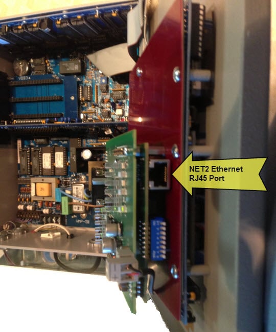
1. Connect a standard RJ-45 Ethernet cable to the Ethernet Module. This should be on a network that is accessible to the PC and the PLC to be monitored.
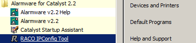
2. Click Start > All Programs > Alarmware v2.2 > RACO IPConfig Tool.
3. The tool will scan the local subnet and display information on any Catalysts that it finds:
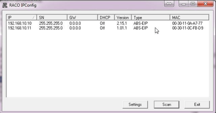
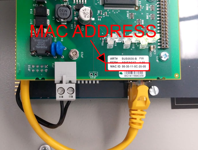
4. If more than one Catalyst is found, you may need to temporarily disconnect one or more of them to determine which the correct one is. Alternatively, you can compare the MAC address printed on the Ethernet Module to the displayed MAC Address.
5. Double-Click on the line containing the IP address of the Catalyst that you want to configure. The configuration window will appear.
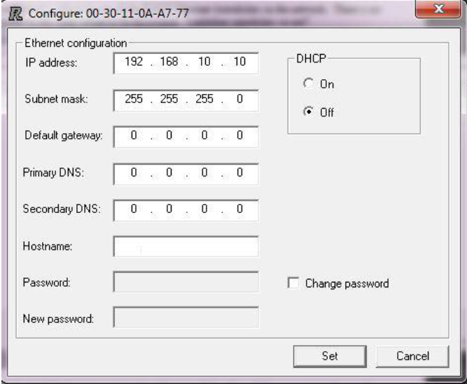
6. It is highly recommended that the Catalyst and PLC be assigned static IP addresses to avoid loss of connectivity if the DHCP server assigns a different IP than the system was configured to use.
7. For a static IP, enter the IP address, Subnet mask, and Default gateway provided by your IT Department. You can leave the DNS entries blank.
8. For a Dynamic IP (DHCP) select the DHCP On option button. You do not have to enter the remaining fields.
9. Close the configuration window and Exit the IPConfig tool.
CAUTION: If DHCP is left on, the PLC can lose connection with the Catalyst if the DHCP server changes the Catalyst’s IP settings.
1. Open a browser on the PC and enter in the Catalyst’s IP in the address bar.The browser should display a page similar to this one. If it does not, or if the displayed configuration is incorrect, then there is a problem that needs to be rectified before the Catalyst will be able to connect.
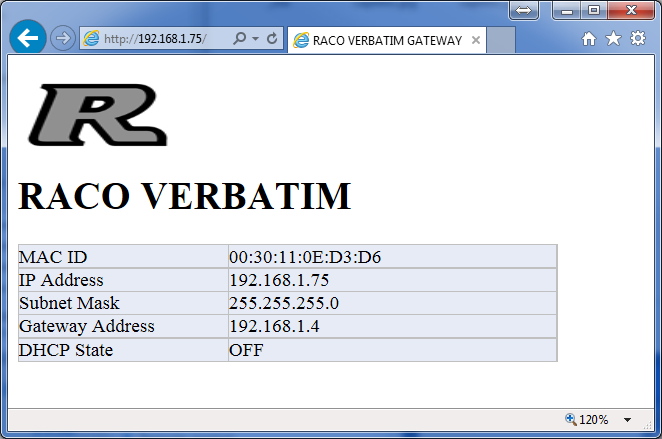
2. The Catalyst Ethernet Module is now configured and ready to receive data from other devices on the network.
Special Note for Modbus TCP Users:
- Our ModbusTCP platform is built upon a non-standard gateway device.
- It follows the Ethernet/IP protocol. i.e. Scanner(PLC)/Adapter(RTU)
- Therefore the PLC (Server) is required to initiate polling.
- First, confirm ModbusTCP is offered within your PLC.
- Next, verify that custom polling is a feature embedded within the PLC's ModbusTCP port. (i.e. device configuration parameters such as "Timeout" typically 50mS, "Retries" typically 3 and "Inactivity Timeout" typically 60 seconds, are available)
It is helpful to have a basic understanding of the Catalyst addressing system to configure alarms successfully.
What is an SNA?
The PLC sends alarm data to the Catalyst via the Catalyst Ethernet Module’s IP address in conjunction with a unique SNA (System Net Address) address. The SNA consists of a Network number, a Node number, and an address on that node. SNA 1*2*00001 would identify Network 1, Node 2, Address 00001. For the Catalyst Ethernet Module, the Network is always 1 and the Node is always 2: 1*2*xxxxx.
The Catalyst can read 1968 addresses in the range from 1*2*00001 to 1*2*01968. Each of those addresses corresponds to one bit (coil). Any of these addresses can be assigned to any Catalyst alarm channel. This also can be represented as a range of 123 16-bit analog addresses in the range of 1*2*40001 to 1*2*40123. The relationship between discrete and analog addressing is described in the following sections.
SNA Data Types
The Catalyst determines if the SNA represents discrete or analog data by the first digit of the SNA. If the first digit is a 0 (1*2*00001) then the data is a single discrete bit. This can be considered as the equivalent of a PLC coil. If the first digit is a 4 (1*2*40001) then the data is a 16-bit integer register that represents an analog reading like pressure or temperature.
SNA Discrete and Analog Register Addressing
This SNA numbering convention is just two different ways of looking at the same data registers. The 16-bit register at 1*2*40001 is composed of the 16 single bit registers 1*2*00001 to 1*2*00016. In other words, SNA 1*2*00001 refers to a bit in the 16-bit register 1*2*40001. SNA 1*2*000016 would be another bit in the SNA 1*2*40001 register. SNA 1*2*000017 would be a bit in the SNA 1*2*40002 register. The exact mapping is covered in Section 2.C.e.
For simplicity in avoiding conflicts, we suggest that you assign the Discrete channels to the lower registers plus some margin for additions and then assign the Analog channels above that range.
To allocate space for 50 Discrete alarms: Each Analog register requires 16-bits. 50 divided by 16 = 3.125 so that would make the first 4 Analog registers unavailable. The first Analog SNA free would be 1*2*40005 as well as all the registers above that.
To determine the exact bits used by an Analog channel: The first bit is found by this equation {(Analog SNA -40001)* 16} +1. Analog SNA 1*2*40005 would be {(40005-40001)* 16} +1 = 65. The Discrete bits used would be SNA 1*2*00065 and the next 15, ending at 1*2*00080.
SNA Discrete to Analog Register Bit Position Mapping
Each Analog register consists of 16 individual bits, numbered from 0 15. There are numerous ways that that the single bit Discrete register addresses can be mapped to these bit positions and can vary with different PLCs. We will discuss the common options here. If these do not match your scenario, please contact Technical Support and we will gladly assist you.
Determining the mapping
- Verify the correct Analog Register address: Monitor the status of the bit in question. Write FFFF-hex to the Analog register that you suspect contains that bit. The bit in question should be set to 1 as FFFF-hex will set all the bits in that register to 1 since FFFF-hex= 1111 1111 1111 1111). If not, then the addressing is incorrect, or there are other issues that must be resolved before continuing. A common problem is that the addressing is off by one, so try the Analog registers that are immediately before and after it.
- Locate the correct byte: Sequentially write F000, 0F00, 00F0, and 000F to the Analog register. Note which value turns the bit on. The bit will be set to 1 when F (1111) is written the byte that contains it.
- Locate the correct bit: Sequentially write 1, 2, 4, and 8 to the byte position that turned the bit on in step 2. If the bit came on when you wrote 0F00, write 0800,0400, 0200, and 0100 to the register. The bit in question will turn on. Converting the number to binary will show the correct bit. If 0400 turned on the bit, then the bit location would be where the 1 occurs in the binary representation: 00000100 0000 0000
RACO Bit Addressing
RACO Catalyst bit addressing for Modbus TCP and EtherNet/IP both conform to the Modbus standard order for consistency. The Discrete registers (bits) are addressed sequentially starting at the most significant bit position.
Modbus TCP and EtherNet/IP Bit Addressing
| 16 bit (Analog) Register 1*2*40001 | 1 bit (Discrete) Register | ||
| Rockwell Tag | Bit Position | Hex Value | SNA |
| Raco.O.Data[0].15 | 0 |
8000 |
1*2*00001 |
| Raco.O.Data[0].14 | 1 | 4000 | 1*2*00002 |
| Raco.O.Data[0].13 | 2 | 2000 | 1*2*00003 |
| Raco.O.Data[0].12 | 3 | 1000 | 1*2*00004 |
| Raco.O.Data[0].11 | 4 | 0800 |
1*2*00005 |
| Raco.O.Data[0].10 | 5 | 0400 | 1*2*00006 |
| Raco.O.Data[0].9 | 6 | 0200 | 1*2*00007 |
| Raco.O.Data[0].8 | 7 | 0100 | 1*2*00008 |
| Raco.O.Data[0].7 | 8 | 0080 | 1*2*00009 |
| Raco.O.Data[0].6 | 9 | 0040 | 1*2*00010 |
| Raco.O.Data[0].5 | 10 | 0020 | 1*2*00011 |
| Raco.O.Data[0].4 | 11 | 0010 | 1*2*00012 |
| Raco.O.Data[0].3 | 12 | 0008 | 1*2*00013 |
| Raco.O.Data[0].2 | 13 | 0004 | 1*2*00014 |
| Raco.O.Data[0].1 | 14 | 0002 | 1*2*00015 |
| Raco.O.Data[0].0 | 15 | 0001 | 1*2*00016 |
Special Note for Modbus TCP Users:
- An understanding of the Modbus mapping is crucial at this point.
- The above table illustrates the 16 bit TAG array defined within the Logix5000 family of AB PLCs. (i.e. Raco:O.Data[0].0~15)
- Within the Modbus realm this is defined/mapped to "Coil" registers. (i.e. 0xxxx)
- This same TAG identified as an INTEGER (not brought down to the bit level) is defined as, Raco:O.Data[0].
- In the Modbus realm it would be identified as an "Output Register" and defined as 4xxxx.
Catalysts shipped prior to 08/01/2015 use a different firmware version. The Modbus TCP mapping is that same as described above. However, the EtherNet/IP mappings are different. RACO will provide a free firmware upgrade if you prefer the new mapping.
EtherNet/IP Bit Addressing (Catalysts shipped prior to 8/01/15)
| 16 bit (Analog) Register |
1 bit (Discrete) Register | ||
| Rockwell Tag | Bit Position | Hex Value | SNA |
| Raco:O.Data[0].7 | 0 |
8000 |
1*2*00001 |
| Raco:O.Data[0].6 | 1 | 4000 | 1*2*00002 |
| Raco:O.Data[0].5 | 2 | 2000 | 1*2*00003 |
| Raco:O.Data[0].4 | 3 | 1000 | 1*2*00004 |
| Raco:O.Data[0].3 | 4 | 0800 |
1*2*00005 |
| Raco:O.Data[0].2 | 5 | 0400 | 1*2*00006 |
| Raco:O.Data[0].1 | 6 | 0200 | 1*2*00007 |
| Raco:O.Data[0].0 | 7 | 0100 | 1*2*00008 |
| Raco:O.Data[0].15 | 8 | 0080 | 1*2*00009 |
| Raco:O.Data[0].14 | 9 | 0040 | 1*2*00010 |
| Raco:O.Data[0].13 | 10 | 0020 | 1*2*00011 |
| Raco:O.Data[0].12 | 11 | 0010 | 1*2*00012 |
| Raco:O.Data[0].11 | 12 | 0008 | 1*2*00013 |
| Raco:O.Data[0].10 | 13 | 0004 | 1*2*00014 |
| Raco:O.Data[0].9 | 14 | 0002 | 1*2*00015 |
| Raco:O.Data[0].8 | 15 | 0001 | 1*2*00016 |
Ethernet_Fail Bit
The Catalyst Ethernet Module constantly monitors the status of the Ethernet connection. If the connection is good (the Ethernet cable is connected and the Catalyst is actively receiving data from the PLC) the adapter will set address 1*2*01992 to 0. If the Catalyst is not connected or is not receiving data, the adapter will set address 1*2*01992 to 1 indicating a failure in the Ethernet connectivity.
We recommend that the first SNA that you configure is the Ethernet_Fail bit so that you can easily verify that the connection is good for the remainder of the setup. It is usually set to the last alarm channel in your Catalyst to leave the lower channels open for standard alarms, e.g. Ch. 56 in a 56 channel Catalyst.
D. Assigning a SNA to a Channel
The user must assign an address to a channel for each register he wants to monitor. They must also specify the alarm condition when configuring each channel.
The process will only be briefly reviewed here as it is covered in detail in the Catalyst manual.
Assign and Configure a Discrete Channel
1. From the PC’s Start Menu, start Alarmware and connect to the attached Catalyst.
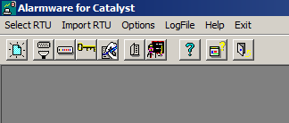
2. In Alarmware, Click on Configuration / Channels
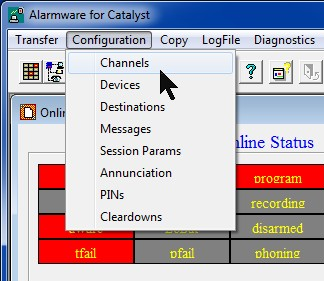
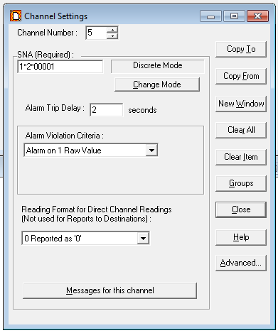
Enter the desired Channel number and SNA. For this example we will use the Health bit SNA 1*2*01992 and Channel 56. The rest of the setting can be left in their default states for most applications. Any SNA can be assigned to any channel.
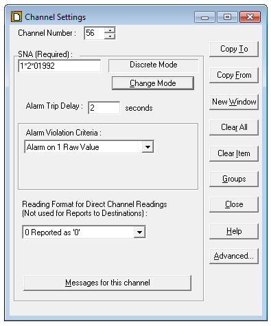
3. Click Change Mode. A window will appear very briefly as the Alarmware downloads the configuration data to the Catalyst.
The mode is the type of data that the SNA contains. Discrete Mode means that the SNA represents a single bit (like a PLC coil). The other mode is Analog Mode, where the address represents a 16-bit integer. The mode is selected automatically based on the SNA.
You can also change the other settings for this channel. This process is the same as when setting a physical address. Refer to the Catalyst manual for that process.
4. At this point the Catalyst is fully configured to send an alarm on channel 56 if communication between the PLC and Catalyst is lost.
Let’s also set a general alarm, for this example on Channel 5, SNA 1*2*00003. Simply change the Channel Number and the SNA to the new values and Click Change Mode. The Catalyst will save and update the settings immediately.
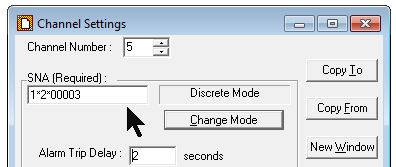
NOTE: Since the Discrete SNA 1*2*00003 uses one of the bits in the 16bit Analog register at SNA 1*2*40001, that register cannot be used to store analog data. Refer to Section C: SNA Discrete and Analog Register Addressing for more information.
5. Repeat these steps to add additional alarms. When you have finished adding alarms, Click Close to exit the Channel Settings window.
Assign and Configure an Analog Channel
1. From the PC’s Start Menu, start Alarmware v2.0 and connect to the attached Catalyst.
2. In Alarmware, Click on Configuration > Channels, Enter the desired Channel number and a SNA in the 4xxxx range (Ch. 2 and 1*2*40005 in this example)
3. Click Change Mode. The mode will change from Discrete to Analog. You can also change the other settings for this channel. This process is the same as when setting a physical address. Refer to the Catalyst manual for that process.
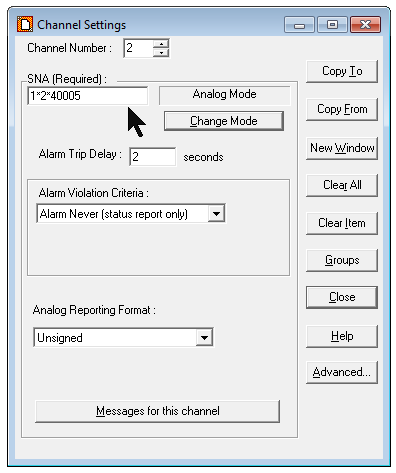
Note: Since the 16-bit Analog register 1*2*40005 consists of the 16 Discrete bits 1*2*00065 to 1*2*00080, those are not available for use as Discrete alarms. Section C: SNA Discrete and Analog Register Addressing.
4. Repeat these steps to add additional alarms. When you have finished adding alarms, Click Close to exit the Channel Settings window.
The Channel Settings also allows the status of an incoming SNA to be interlinked to a SNA output channel. Once each scan cycle, the value of the input SNA is written to the output SNA. Refer to the Advanced Channel Settings section of the Catalyst manual for information for further information and configuration instructions.
This completes the Catalyst Setup. You may now perform the “Testing the Catalyst Ethernet Functionality” procedure to verify its operation. This consists of using a PC based program to simulate reading and writing the Catalyst SNA addresses.
The test consists of using a testing utility to read and write the Catalyst’s SNA registers. This test will tell whether the Catalyst is properly configured and responding to Modbus TCP commands prior to connecting it to a PLC. Since the Catalyst uses the same hardware and configuration internally for Modbus TCP and EtherNet/IP, it will also test EtherNet/IP systems.
If the Catalyst passes this test and the PLC is still not able to set alarms then investigate the connectivity between the PLC and Catalyst and that the PLC is writing to the correct address.
CAUTION: The testing software must be run from a PC that is on the same subnet as the Catalyst. It is strongly advised that the PC and the Catalyst be on an isolated network during testing. Since the test software can send out Modbus commands, there’s a small chance that the user could accidentally send commands to a PLC on the same network. This could result in equipment damage and personnel injury.
Install the utility
1. Enter this URL into a browser: https://www.baseblock.com/PRODUCTS/demosoftware.htm
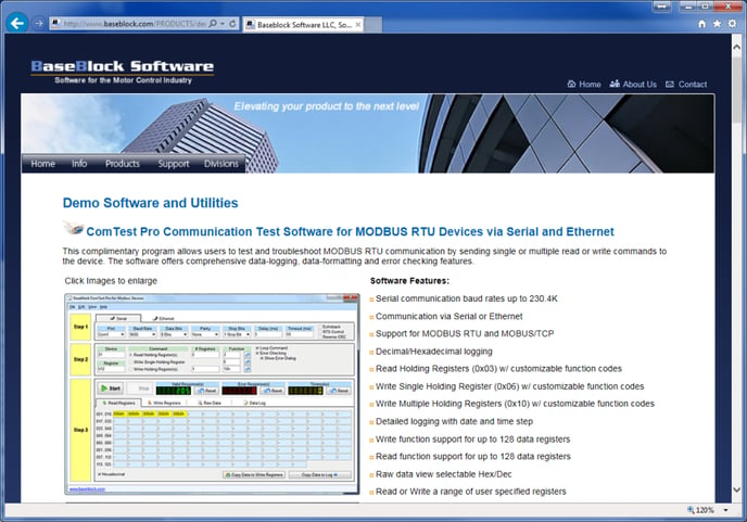
2. Scroll down and Click the Download Now button.
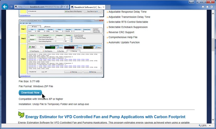
3. Download the file BBCOMTESTPRO.zip file to your computer. This process will vary depending on your browser.
4. Double-Click the zip file to open the zip file. Double-Click the setup.exe file that’s inside the zip file. You do not need to extract the zip file contents.
5. When the setup starts, Click Yes at the Windows User Access Control window and the ComTest Pro installation will continue.
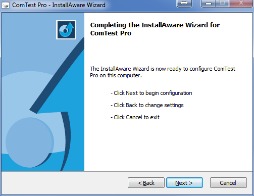
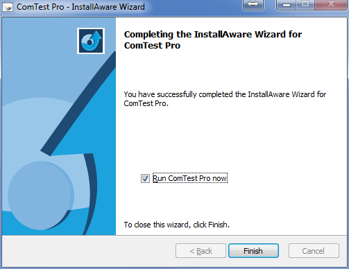
6. Click Next. If the installer notifies you that a restart is necessary, then restart your computer. Otherwise the completion window will appear. Uncheck the check box if you don’t want to run the program now. Click Finish.
Configuring ComTest Pro
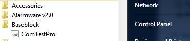
1. If ComTest Pro is not running, start it by Clicking: Start Menu > All Programs > BaseBlock > ComTest Pro
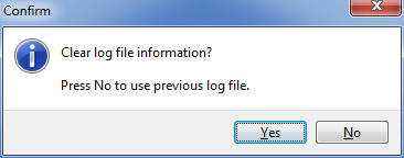
2. At the Confirm window Click Yes.
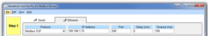
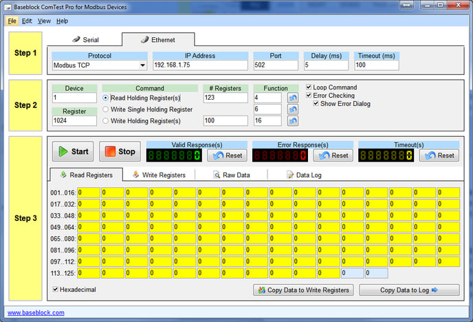
3. The main ComTest Pro window will open. The Help menu (F1) has a very good explanation of the program options so they will not be repeated in detail here. The initial screen may differ slightly from this example. Click the Ethernet tab.
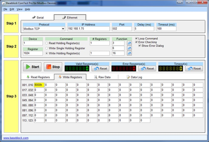
4. In Step 1, enter the settings as shown here, except enter the actual IP Address of your Catalyst.
5. In Step 2, select (*) Read Holding Register(s). Enter the settings as shown here for testing. ComTest Pro register 1024 corresponds to SNA 2*2*40001 in the Catalyst.
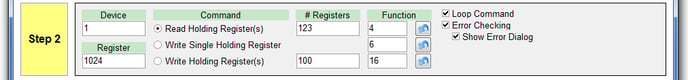
6. The registers that are selected to be read will be highlighted in yellow. ComTest Pro is now configured to read 123 registers from 1024 to 1147 (SNA 1*2*40001 – 40123) in the Catalyst) or to force 100 registers 1024 to 1124 (SNA 1*2*40001 – 40123). This is the standard testing setup.
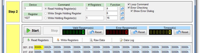
7. Alternatively. you can read a single specific register by setting # Registers to 1 and entering the desired register in the Register box. We recommend that you test the addresses that we provide in this procedure first. This will verify the operation without adding additional variables to the testing. For example this will read and write only register 1027 (SNA 1*2*40004) and display the result in the 00001h textbox that is highlighted in yellow:
This procedure sets up the Catalyst to give an alarm when it receives the correct data from ComTest Pro.
Verify the Catalyst’s Ethernet Connectivity
This section is a brief recap of the Catalyst setup in Section 2. If you have just completed that section, you may skip these steps.
Read Testing
Read testing verifies the basic connectivity and functionality of the Catalyst.
1. Check that ComTest Pro , Alarmware, and the Catalyst are still setup as described in the previous steps.
2. Click the Start button in Step 3 of the ComTest Pro screen. The program will start repeatedly reading and displaying the selected registers’ values. The Valid Response(s) counter should start incrementing about once a second. This indicates that the program can successfully read from the Catalyst.
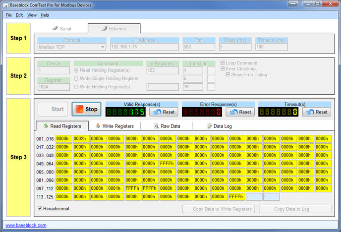
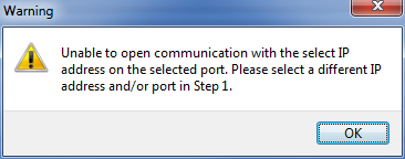
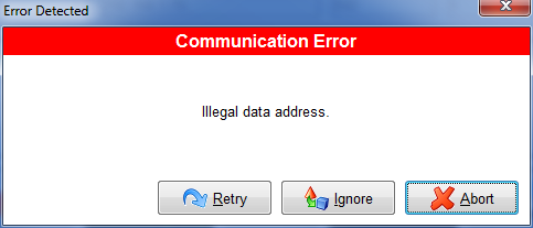
3. The registers will all read 0000h unless data has previously been written to them. If there is a communication or addressing problem ComTest Pro will display an error popup such as these. Investigate and resolve the problem before continuing. If the read testing is successful, Click Stop and then proceed to the write testing.
Write Testing
CAUTION:
Since the test software can send out Modbus commands, there’s a small chance that the user could accidentally send commands to a PLC on the same network. This could result in equipment damage and personnel injury.
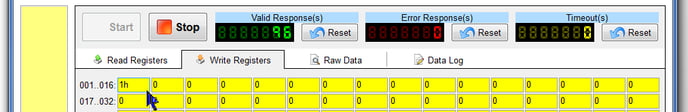
Determining the correct data to enter for writing requires some math. We can skip the math by using these predetermined numbers to see if the Catalyst is accepting data. To skip the math, set the Catalyst to alarm on SNA 1*2*00001. Enter 0001 in the first yellow box. The ‘h’ will be added automatically. Proceed to Step 1 in the procedure below.
To test a specific SNA, we need to determine the correct integer required to enable the specific alarm SNA. ComTest Pro can only write to a complete 16-bit register. It cannot write a single bit. To trigger a single bit discrete alarm SNA (1*2*00001 in our example) we must determine the 16-bit HEX number that corresponds to that bit. Divide the address by 16 then add 1 to the quotient to determine which 16-bit register that it is in.
For 1*2*00001: 00001/16 = 0 R1. 0+1 = 1 so 00001 is located in the first register 001.
The remainder will indicate the bit in that register. The HEX value that must be entered to turn that bit on is: 2^R (2 to the R power) converted to HEX. With R1, 2^1 = 1 so enter 0000h in the first register square.
For 1*2*00147: 157/16 = 9 R13, 13+1=14 so use register 014. 2^13=8192d, = 2000 HEX so enter 2000h in register 014.
1. In Step 2 of the ComTest Pro window, select (*) Write Holding Register(s). Enter the settings as shown here for testing. ComTest Pro register 1024 corresponds to SNA 1*2*40001 in the Catalyst. In Step 3, enter FFFF.
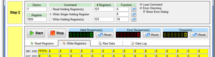
2. Click the Start button in Step 3. The program will start repeatedly writing the selected registers’ values. The Valid Response(s) counter should start incrementing about once a second.
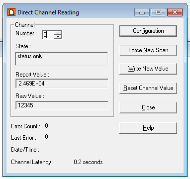
3. In Alarmware, Double-Click on the numbered alarm indicator to monitor the Direct Channel Reading. Change the Channel Number to the desired channel.
4. The State should be ALARM and Report Value and Raw Value should be 1.
5. Click Stop. Enter 0 in the ComTest Pro register and Click Start again.
6. The Raw Value should be 0. Click Stop to stop writing data.
7. Repeat these steps for all the discrete SNAs to be tested.
8. To test an Analog channel enter a decimal integer value in the textbox of the register to be tested. A decimal value is entered by entering the number without the h suffix. (12345 in Register 1 for our example). Remember that Register 1 corresponds to SNA 1*2*40001 in the Catalyst. Since the register is 16-bit, the maximum value is 65535. Any value entered greater that that will indicate 65535 on the Catalyst.
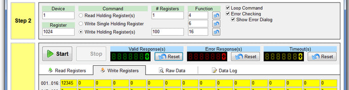
9. Click Start. Observe the Alarmware Direct Channel Reading window. The Raw value should equal the same number that was entered in the ComTest Pro register. The Report Value applies any scaling that has been added; we entered a gain of 2 in this example. See the Catalyst manual for information on scaling and other aspects of the channel setup.
10. Click Stop to stop writing data.
11. Repeat these steps for all the Analog SNAs to be tested.
Once the read and write testing are completed satisfactorily, exit the Alarmware and ComTest Pro programs. You may now proceed to configuring and testing the PLC with the assurance that the Catalyst is responding properly.
If this testing is successful but your PLC cannot activate alarms on the Catalyst then there’s a communication or addressing problem with the PLC. These problems are best resolved by contacting your networking and PLC support options. RACO Technical Support will work with you and them to resolve the issues as they relate to the Catalyst.