|
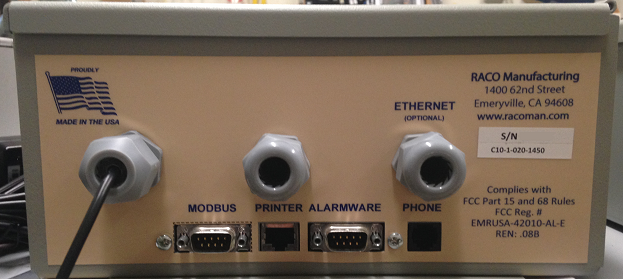
This technical note explains how to interface the RACO Catalyst Ethernet auto dialer directly to Ethernet networks. Specifically, this note will detail connectivity between the new Ethernet/IP option for the Catalyst and the Allen-Bradley RSLogix500 PLC platform. Before We Begin, it is assumed that the reader of this tech note is already familiar with the basic operation and programming method of both the Catalyst product and Rockwell Automation software to include RSLinx Classic and RSLogix5000. The Catalyst Ethernet supports one communication port, named NET 1. The Factory provided Ethernet cable attaches to the communication connector (ETHERNET) that is mounted on the bottom panel of the Catalyst chassis.
This Ethernet version of the Catalyst supports equally the ModbusTCP or the EtherNet/IP networks over the Ethernet port. The main purpose of connection to the Ethernet network is to get the PLC data natively instead of connection on other external network bridges. Procedural Steps to Achieve Communications: |

Click the  next to the title to expand that section.
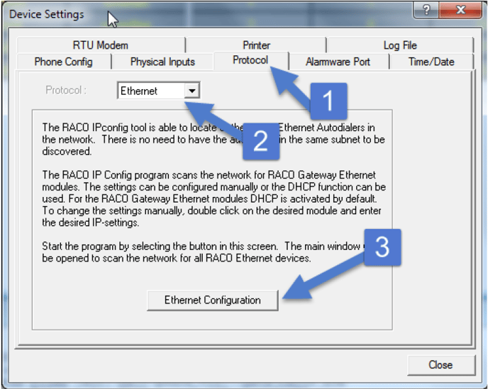
 Setting the Ethernet/IP Address / Programming RSLogix500 Software Setting the Ethernet/IP Address / Programming RSLogix500 Software |
||
|
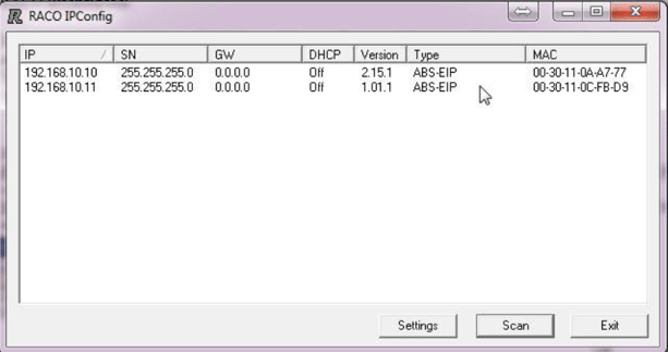
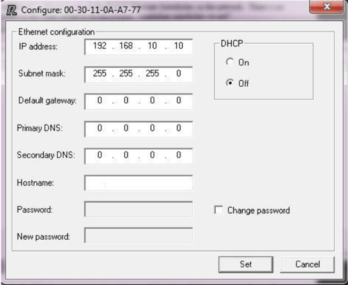
Once the program is launched it will automatically scan your Ethernet port looking for RACO Ethernet auto-dialers. Click the SCAN button to re-scan the network. The RACO IPconfig tool can be used to configure the IP settings of all RACO EtherNet/IP modules. Also, it is able to locate all the RACO Ethernet auto dialers in the network. There is no need to have the auto dialers in the same subnet to be discovered. The settings can be configured manually or the DHCP function can be used. For the RACO Catalyst Ethernet modules DHCP is activated by default. To change the settings manually, double click on the desired module and enter the desired IP-settings as seen below.
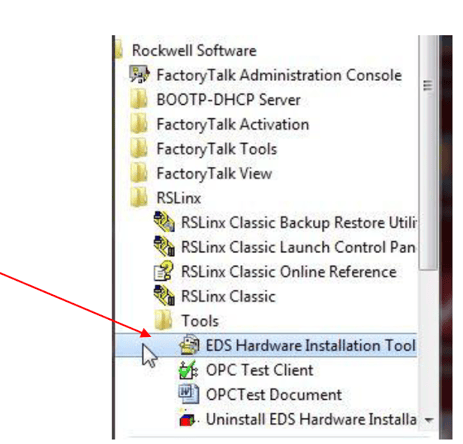
Ensure each node on the network has a unique IP address. EDS Hardware Installation tool An Electronic Data Sheet (EDS) file, that identifies your RACO Auto dialer within Rockwell RSLinx environment, needs to be installed onto your system via the EDS Hardware Installation Tool. This install utility would typically be located under your RSLinx/Tools directory.
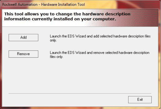
Once the EDS Hardware Installation Tool has been launched, select the path/location of your RACO EDS file. This file was included within your Alarmware CD that was shipped with the Catalyst, The EDS file should be copied over to your system and installed via the EDS Hardware Installation tool illustrated below. The file is located on the CD in the \RACO\Alarmware20 folder
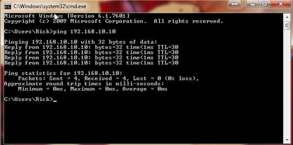
STEP #3 Confirming Ethernet connections with all applicable devices Command Prompt (CMD) Via your operating system, launch CMD.exe. You should be able to PING the RACO devices on the network. Make sure your PC's IP address shares the same SUBNET. A successful response from your RACO auto-dialer would appear similar to the photo below.
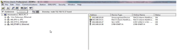
RSLinx Classic Following confirmation of RACO products on your network via the command prompt, it would be a good practice to next open your RSLinx Classic software and view the online status via RSWho. This technical note assumes that one is familiar with RSLinx Classic software and can configure the appropriate driver to suit. Via RSLinx Classic you should now be able to observe the RACO auto-dialer as active within the RSWho form.
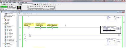
Step #4 Programming RSLogix500 software to communicate with the Catalyst Ethernet Configuration within the RSLogix500 Environment Embedded within the SLC 5/05 processor, on Channel 1 is an Ethernet port. This port will support the CIP protocol via the EtherNet/IP Explicit Message Instruction. (EEM) The EEM instruction will compile a CIP type packet of data and transmit/receive to the desired IP destination. Configuration of the EtherNet/IP Explicit Message Instruction. (EEM) This instruction can be used with any SLC 5/05 processor at OS firmware level Series C, FRN 10 or higher. The EEM Instruction is located under the ”Input/Output” tab of the "Tab Instruction Bar". Drop one onto your ladder as an output and assign a block of Integer Register values. NOTE: To READ and WRITE data the EEM instruction must be triggered. (i.e. the rung must go high) In our example, once triggered we've enabled the EEM instruction for 100ms provided no instruction error.
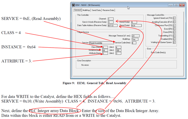
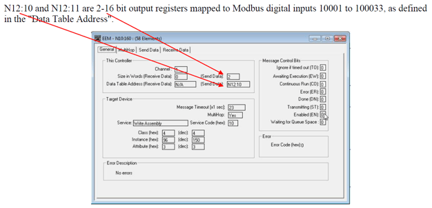
Once the Control Block of Integer Registers has been assigned, press ENTER. This will launch the EEM Configuration dialog, see below. The dialog will appear with the GENERAL tab open. It is here we assign the messaging details. The RSLogix500 platform via the EEM instruction will communicate to the Catalyst via Explicit messaging. Every Integer array or block READ or WRITE will require its own EEM instruction. For data READ from the Catalyst, define the HEX fields as follows:
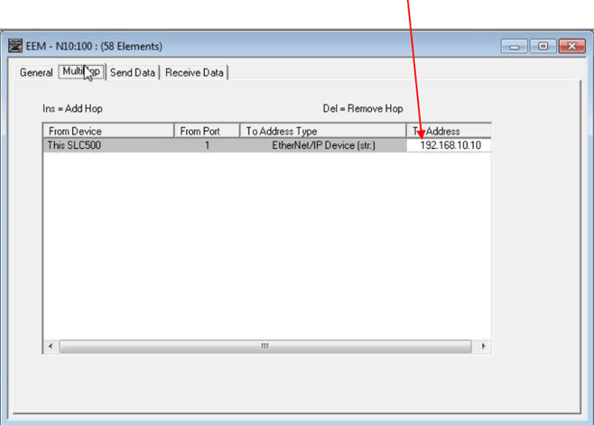
Once all fields in the GENERAL tab have been completed, open the MULTI-HOP tab and enter the Catalyst's IP as defined with the RACO IPconfig tool, under the "ToAddress" field. Then close the dialog. Download or if online, Assemble your edits and you are ready to test.
|
||
|
|
| Modbus Protocol Overview |
|
STEP #5 Modbus Protocol Modbus RTU is a serial communications protocol originally published by Modicon, for use with their programmable logic controllers. Due to its inherent ease of deployment and maintenance, the fact that it is royalty free and well suited to a variety of applications it has earned its place as a communication standard amongst the Industrial Control community.
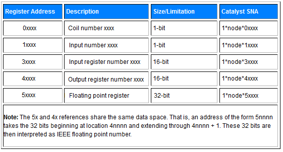
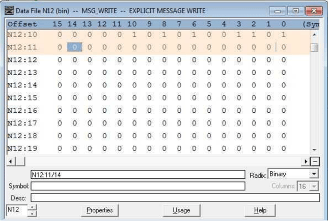
The above table illustrates the Modbus data file convention within the Catalyst. These Modbus Register Addresses map to integer files defined within the Block of TAGs defined in the EtherNet/IP Explicit Message Instruction. (EEM) It is important to recognize the differences when addressing coils and registers. The Modbus convention allows for the mapping of various Modbus type registers to unique internal memory locations within the PLC. For Example:
For Example:
This allows flexibility to look at data as input registers, holding registers, coils, etc., as many Modbus masters don’t have all functions implemented. Important: Since both Output Register (4xxxx) and Holding Register (5xxxx) data types use the same data area at the RACO end, the Holding Register (5xxxxx) uses two consecutive 16 bit addresses that are interpreted as a 32 bit floating point number. (i.e. 5xxxx & 5xxxx+1) Not unlike the Holding Register, the Output Register (4xxxx) also reserves two consecutive 16 bit words however the extended word is left blank. Similarly when addressing the input register (3xxxx), allow for two consecutive 16 bit words, keeping in mind the extended word is reserved but not used. Hence, consecutive addressing of both Input and Output Registers will appear as follows: For example, first Input Register address point 30001, 2nd address point 30003, 3rd address point 30005, etc. |
| Communication Registers |
||
|
In order to better support the new Ethernet/IP card, we have provided the addition of a Communication Health Bit. As this is a new option, it has yet to be included within the Catalyst User's Manual. This can be easily configured to monitor Ethernet connectivity. Should the Catalyst lose it's connection to the Ethernet/IP master, the health byte 40124 will go from 0 to 256 (i.e. REGISTER #124, BIT #8) or the bit 01992 will go from 0 to 1. Normally LOW, should loss of communications occur, the bit will go HIGH. It is recommended to ALARM when the state goes HIGH. To enable the loss of communication alarm, program the Catalyst to ALARM when HIGH address 01992. Assign this ALARM to any available channel. (i.e. Channel 56) You may choose any available channel for this function (shown here using channel 56). We recommend using a channel near the end, i.e., 56, 96 or 256 depending on your model. Note that Normal means actually talking to the PLC. You would get an alarm if you are plugged into the Ethernet, but the PLC is not communicating, or if you are not plugged into the Ethernet. Important: To announce communication interruption alarms; Make sure to record alarm messages by following ‘Message Recording and Reviewing” Starting on page 7-47 of the main Catalyst manual.
|
| Quick Start |
|
STEP #9 Quick Start Step #1 - Set up Catalyst
(Note that although some Catalyst parameters can be configured with the front panel keys, Catalyst Ethernet will need to be configured with Alarmware) Step #2 - Set up Ethernet side of Catalyst
Step #3 - Set up PLC
Step #4 - Set up Network remote channels
|