Field Installation Instructions
Refer to the diagram of the front panel to locate connections for these wires.
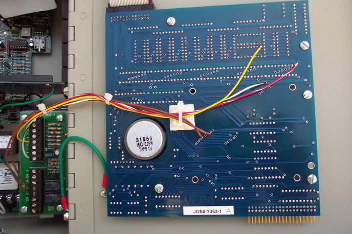
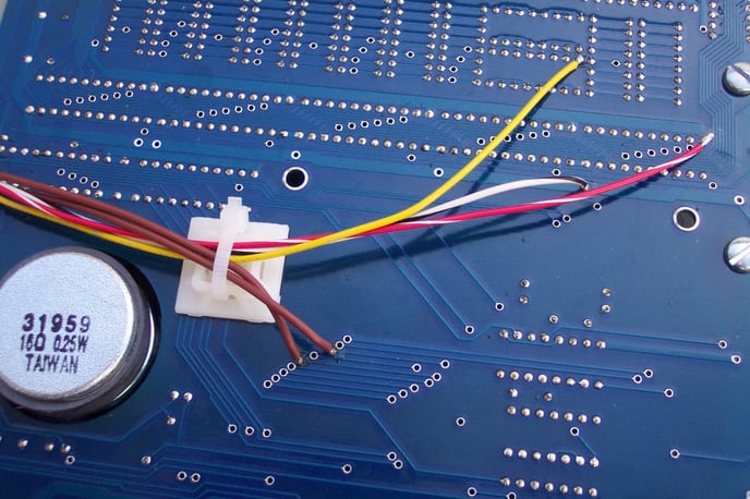
1) Power - Solder connections TS1-1 (red) and TS1-8 (black) to front panel as shown.
2) Front Panel access to Disarm switch Solder connections TS2-4 to Disarm via and TS2-5 to the Common via (brown wires).
3) Solder connection TS1-5 (yellow) to the Arm/Disarm LED via on front panel as shown.
4) Jumper JP2 should be on, jumper JP1 (if present) should be removed.
BICM2 for Verbatim / Verbatim Gateway Overview
BICM2 for Verbatim / Verbatim Gateway Front Panel Detail
(Click to Enlarge)
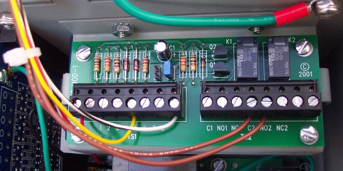
BICM2 for Verbatim / Verbatim Gateway Module Detail
OPERATION
This module is factory configured and wired so that one of its two relays (K1) activates when the dialer is disarmed. It also allows the Armed/Disarmed status to be toggled via a remotely located dry contact momentary switch.
Pushing the external push button activates relay K2. The NO contacts on this relay go to the front panel “Arm/Disarm” switch, which will toggle the Arm/Disarm function.
Relay K1 monitors the “Arm/Disarm” LED. With the “Arm/Disarm” LED off, relay K1 will be off. When the LED goes on (Disarmed), K1 is activated. The NO contacts on TS2 will close to turn on an external “Disarmed” light (see below). Alternately, you can use NC contacts on TS2 to light an “Armed” light which will go out when the unit is Disarmed.
Armed /Disarmed indication: Contacts from C1 to NO1 close when the product is Disarmed.
The contacts will pulse on and off in concert with the Disarmed light on the front panel unless the module is factory configured to stay closed on Disarmed status. Contacts from C1 to NC1 close when the product is Armed (with no pulsing on and off in any case). Exception: when product is Off, contacts from C1 to NC1 are always closed and C1 to NO1 are always open.Armed/Disarmed control: Connect a momentary, normally open switch to TS1 (upper terminal strip) terminals TS1-4 and TS1-7. Each time the switch is momentarily closed, the armed/disarmed state changes.
Make wiring connections to terminal strip TS2 (lower terminal strip) so that the contact closures provided by the module will activate remote indicating devices as needed.
It is imperative that this low voltage switch connection not have any other voltage imposed from any other circuit. Extraneous voltages can damage the Verbatim Autodialer. Do not run the wires in close parallel with AC power wiring.
Important note on limited contact power ratings:
The relay contacts on this module can handle only limited amounts of current and voltage. Thus intermediate relays may need to be installed depending upon the load presented by the remote indicating devices.
At 120 VAC, the current limit is ½ amp, which includes any inrush current. Incandescent bulbs over 10 watts at 120 VAC should not be connected directly to these contacts because of their substantial inrush current which is many times their operating current.
For voltages under 60 VAC, the current can be up to one amp.
For DC voltages, the current must not exceed one amp, and the product of current and voltage must not exceed 30 Watts.