 This technical note explains how to interface the RACO Verbatim Gateway system with the Allen-Bradley MicroLogix 1100 and 1400 models of PLCs via Ethernet. Both the MicroLogix 1100 and 1400 PLC contain an Ethernet / IP port. This port along with the 1761-NET-ENI allows the Verbatim Gateway to perform its alarm notifications and monitoring functions using the existing wiring to Allen-Bradley MicroLogix 1100 and 1400 PLCs as inputs via Ethernet. This technical note is applicable for all Verbatim Gateway models.
Requirements
 RACO-supplied components:
- Verbatim Gateway (any model)
- 515VAB-ENI cable
Allen-Bradley-supplied components:
- MicroLogix 1100 or 1400 PLC
- 1761-CBL-PM02 (RS232 programming cable)
- 1761-NET-ENI (DF1 to Ethernet protocol converter)
- Copy of ENI / ENIW Utility software (available free via www.AB.com)
- Either a crossover Ethernet cable or standard Ethernet cable connected through a Hub / Switch
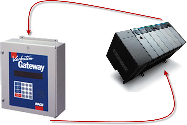
In order to facilitate Ethernet communications, RACO provides a 515VAB-ENI cable that connects the Verbatim Gateway to the 1761-NET-ENI. This cable has the RJ-45 connector required at the Verbatim Gateway end and the 8-pin mini at the other end that connects to Port 2 (RS232) of the 1761-NETENI card.
Once this cable is connected, only Ethernet-related hardware is required.
Communication Setup for the 1761-NET-ENI
The 1761-NET-ENI provides Ethernet / IP connectivity to all DF1 full duplex devices.
 STEP #1 — Configure the 1761-NET-ENI card. The ENI / ENIW Utility program (free download from www.ab.com) is required.
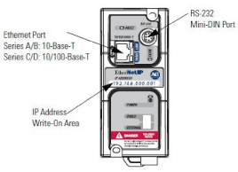
STEP #2 — Connect the 1761-CBL-PM02 serial cable. The serial cable connects your PC to the unit via the RS-232 port as illustrated. (right)
STEP #3 — Ethernet port is easily found just below and left of the RS-232 port.
STEP #4 — The center of the unit contains a blank field available to illustrate your custom configurable IP Address.
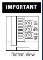 STEP #5 — An external isolated 24vdc power source should be used and wiring terminals can be found at the bottom of the unit. In addition to assigning its own IP address, the ENI / ENIW Utility program maps the DF1 node address of the PLC, as defined in the Verbatim Gateway, to the PLCs IP address.
STEP #6 — There is a selector below for power. Make sure the switch is in the “external” position. External power is recommended always.
STEP #7 — Launch ENI / ENIW software. Once the program is launched, you will observe seven available tabs from which to select.
STEP #8 — Choose the "Utility Settings'" tab. Select the COM port and baud rate that your PC will be using.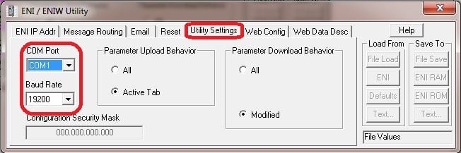
STEP #9 — Select the "ENI IP Addr" tab. Next, set the 232 Baud Rate to "Auto." Set the IP address of the 1761-NET-ENI. Ensure the ENI series is correct. Provide the "ENI IP Address," "Subnet Mask" and "Gateway" where necessary.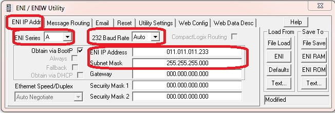
STEP #10 — Our next step prior to downloading / saving is to map the IP address of your Micrologix to an available NODE / STATION address. Under the "Message Routing" tab, assign a DF1 NODE / STATION number (range from 0–49) to the IP address of your Micrologix. In this case we've assigned the node number 2.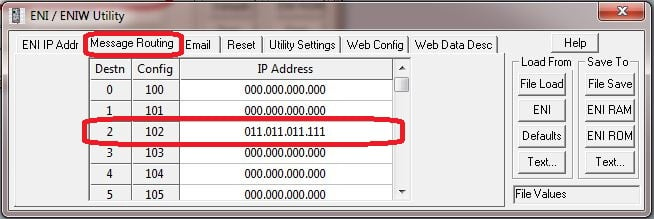
Now we are complete with the ENI / ENIW configuration utility and we can save and download our application.
STEP #11 — Observe that there are separate memory areas to save the application, either ENI RAM or ENI ROM. Use the ENI ROM selection.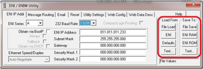
STEP #12 — Once you've downloaded your application you may save and close the Utility. The flashing "Fault" LED on the 1761-NET-ENI indicates an incompatible IP or Subnet. If the "Fault" LED is off following a download you are now able to proceed.
STEP #13 — At this point you should also be able to ping the IP Address of your 1761-NET-ENI, and are ready to configure your Verbatim Gateway.
Communication Setup for the Verbatim Gateway
The following seven-step procedure will configure your Verbatim Gateway to link its Remote Channels (RC) to your PLC addresses over Ethernet highway, via DF1. Once linked, the Verbatim Gateway will monitor RC status and Alarms according to your settings.
Connections to the PLC are via the onboard RJ45 port or NET. With the V232/485, two NET / ports are provided. NET ID = 1 is dedicated to the DH485 protocol and NET ID = 2 is configurable for either Modbus RTU Master or DF1. (Refer to table #1.)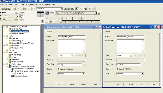
STEP #1 — Protocol Driver (4906)
When setting the Protocol, Node Address and Communication parameters, it is good practice to include the NET ID. (i.e. 4901, 4903, 4904, 4905 and 4906) Insert the NET ID immediately following the parameter number, as defined below.
- As per Table #1 above, set the Protocol Driver to DF1 on NET 2.
- Key in the following: 4906 2 <point> 3 <enter>
- To read the Protocol Driver for NET 2, key in the following: 4906 2 <enter>
STEP #2 — Node Address (4905)
Choose a unique DF1 NODE address for the Verbatim Gateway. As illustrated above, we’ve already selected NODE / STATION 2 for the PLC. DF1 allows NODE addresses to range from 1–64 however, the NET-ENI card can only access 0–49. Therefore a valid range is from 1–49.
- For example, set the Gateway NODE address to “1” by using code 4905.
- To set the NODE address of NET 2, key in the following: 4905 1<point> <2> <enter>
- To read the NODE address of NET 2, key in the following: 4905 1 <enter>
STEP #3 — Communication Parameters (4901, 4903, 4904)
Select the communication parameters. These must match with the driver settings on your PLC.
The following communication settings are required to communicate with the 1761-NET-ENI card:
- BAUD rate = 19200 for 19200 on NET 1, key in the following: 4901 2<point>19200 <enter>
- Stop Bits = 1 for 1 on NET 2, key in the following.., 4903 2<point> 1 <enter>
- Parity = NONE for “NONE” on NET 2, key in the following: 4904 2<point> 0 <enter>
- Parity definition: 0 = NONE, 1 = ODD, 2 = EVEN, 3 = SPACE, 4 = MARK
STEP #4 — Confirmations (4900, 4901, 4930, 4946)
Step #4 will validate all preceding steps, provided both your serial and Ethernet cabling is in place.
- To verify successful network communications on NET 2, key in the following: 4930 <point> 2 <enter>
- To read the BAUD rate for NET 2, key in the following: 4901 2 <enter>
- To verify that communication settings reflect the above, at NET 2, key in the following: 4900 2<enter>
- To verify active node addresses on NET 2, key in the following: 4946 2<enter>
STEP #5 — Set Defaults
This step simplifies Channel Configuration. (i.e. Step 6)
By setting to Default both the NET ID and NODE / STATION address, it is no longer necessary to reference them when setting Channel Configuration. Set the following to DEFAULT.
- 1 NET ID, used to communicate via DF1 (i.e. “2”)
- 2 NODE / STATION address of the target PLC (i.e. "2" as assigned in the NET-ENI / W utility)
- To change the NET ID to 2, key in the following: 4910 2 <enter>
- To confirm the NET ID, key in the following: 4910 <enter>
- To change the PLC NODE / STATION address to “2” of NET 2, key in the following: 4911 2 <enter>
- To confirm PLC NODE / STATION address, key in the following: 4911 <enter>
STEP #6 Channel 1 & 2 Configuration (4501) (4502)
Since Verbatim Gateway channels are completely compatible with the logical and I/O addressing scheme for the file structure of the SLC series processors, the table below should look familiar.
Table #2 shows the Allen-Bradley supported address types available to link to Verbatim Gateway channels. Indirect, indexed and symbolic addressing schemes are not supported.
The two examples below illustrate the link to the PLC data table (via DF1, Table #2) to the Verbatim Gateway channels.
- Example #1
To link B3:0/0 in the PLC to Channel 1 as per the PLC file structure illustrated above, key in the following: 4501 <point> <shift> <B> <3> <shift> <:> <0> <shift> </> <0> <point> <enter> - To verify the current address entered, key in 4501<point><enter>
- To read address value, key in 4001<point><enter>; this will read the actual PLC value assigned to Channel 1.
- Example #2
To link N7:0 in the SLC PLC to Channel 2 as per our PLC file structure illustrated above, key in the following: - 4502 <point> <shift> <N> <7> <shift> <:> <0> <point> <enter>
- To verify the current address entered, key in 4502<point><enter>
- To read address value, key in 4002<point><enter>, this will read the actual PLC value assigned to Channel 2.
STEP #7 — Assignment of Alarm Conditions
Having created and tested your Remote Channels in Step #6, you are now able to assign alarm conditions Channel #1, configured as Discrete, is either ON or OFF.
Should this channel be linked to a “Failsafe” point in the PLC, (i.e. ON = NORMAL, OFF = ALARM) we would alarm when OFF. In this case, we would key in 45 01 2.
- To alarm when ON (i.e. signal is HIGH), key in the following: 45 01 1
- To alarm when OFF (i.e. signal is LOW), key in the following: 45 01 2
- To read Alarm status for Channel 1, key in 4001<enter>
- Channel #2, configured as Analog, operates within the range from 0–65, 535.
Should this channel be linked to a pressure signal in PLC, and the process requires that pressure remain within an acceptable level, otherwise ALARM (for example, BELOW 10,000 AND ABOVE 30,000), we would key in the following:
- To alarm when the analog signal falls below a value, for example 10,000, key in 45 02 5 10000
- To read the LOW set point alarm, key in the following: 45 02 5
- To alarm when the analog signal rises above a value, for example 30,000, key in 45 02 6 30000
- To read the HIGH set point alarm, key in the following: 45 02 6