Allen Bradley
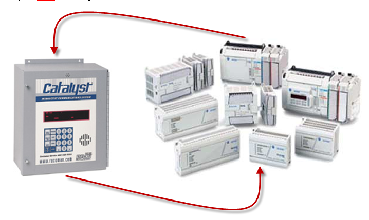
 This technical note explains how to interface the RACO® Catalyst® system with many of the Allen-Bradley® MicroLogix™ family of PLCs. This allows the Catalyst® to perform its alarm notifications and data logging functions using the existing wiring to Allen-Bradley® MicroLogix™ as inputs via data communications.
Required Components
The following components are required.
RACO® supplied components:
- Catalyst® (C10-S-020-1450, C10-1-020-1450, C10-2-020-1450 models)
- Alarmware Software version 1.87
- 707CAT-PC15 Cable (Qty-2)
 Allen-Bradley® Supplied Components
- MicroLogix™ PLC as listed in the table below
- RSLogix™ 500 software version 8.10.00
- 1761-CBL Cable
The table below lists the MicroLogix™ PLCs containing a native Modbus RTU Slave driver.
| Modbus RTU Slave Driver is available within the following MicroLogix (tm) PLC's | |
| Model # | Series # |
| 1100 | A & B |
| 1200 | A & B & C |
| 1400 | A |
| 1500 LSP | B & C |
| 1500 LRP | B & C |
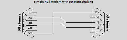
In order to facilitate data communications via Modbus RTU Master/Slave over RS232 data interface, a simple NULL Modem serial cable is required and parameters need to be set at both the Allen Bradley and RACO Catalyst.
No additional hardware is required.
Communication setup for the Allen Bradley Micrologix.
When configuring communications for the Allen Bradley, a communication cable and either the RSLogix500 or RSLogixMicro software are required.
A popular choice for communication cable is the 1761-CBL cable, available from Allen Bradley. This cable has a round 8-pin mini DIN plug on one end and the 9 pin female (computer side) on the other. This cable connects to Channel “0” in the Micrologix, where the DF1 Full Duplex driver by default is ready to communicate to your RSLogix software.
Once your RSLogix file is open, you will need to set communications driver to Modbus RTU Slave. To do this, open the Channel Configuration form and select an available channel other than Channel “0”, where possible.
Caution: it is not recommended to configure communications to Modbus should your PLC have only a single communications port, as Channel 0 should remain available to RSLogix software for program upload/download and monitoring.
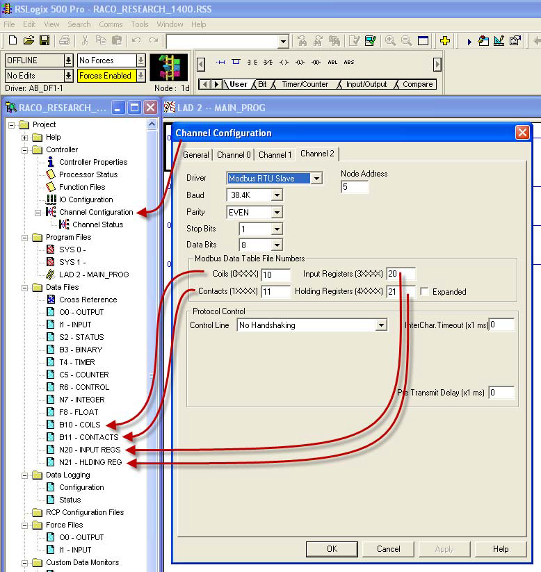
As shown above, the Channel configuration form has 4 tabs, General, Channel 0, Channel 1 and Channel 2. Since we will reserve Channel 0 for RSLogix software, we will select the Channel 2 tab. (select Channel 1 if Channel 2 does not exist). Once the Driver field is clicked a drop down menu of driver choices will be visible. Select Modbus RTU Slave, as shown. Next, select a unique Node Address. Catalyst default is ‘1’ so anything other than 1, up to 256, is acceptable. Both the Baud rate and parity should match with the Catalyst.
(Catalyst default; Parity = EVEN, Stop Bits = 1)
We then need to select the PLC data files to link to the Modbus file convention.
Any available data file can be utilized. The available file numbers are 3, 7 and 9 – 255.
When using the Null Modem cable as defined above, ‘No Handshaking’ should be selected for Control Line.
When selecting the data files ensure that they exist. If the files do exist, ensure the elements
within the file exist and, are not being utilized elsewhere in your program.
In the example, above , new data files were created and named exclusively for Modbus communications. (high-lighted in yellow)
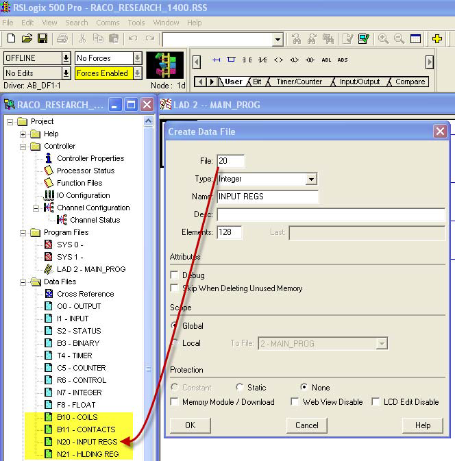
Once a file number has been assigned select the data type. Type the name you wish to call the file in the ‘Name’ field. Our name follows the assignment as per Modbus. (see Table #1)
Micrologix only allows Binary or Integer type data files to be linked to the Modbus convention. Floating point files are not currently accepted. (i.e. 5xxxx)
In our example, 128 elements were selected. In the case of both ‘Coil number’ and ‘Contact number’ where an address is only a single bit, this translates to 2048 available addresses. (i.e. 128 * 16 bits)
In the case of ‘Input Register number’, 128-16 bit integer addresses were available.
In the case of ‘Output Register number’, 128-16 bit integer addresses are available.
Note: although we have assigned data tables 128 words in length, we are bound to the limitations on the Catalyst end. Please refer to the part numbers listed above when selecting a unit to suit your application.
For example, part # 703C10-2-020-1450 offers up to 256 user configurable channels available to communicate with your remote PLC in either word or bit format.
Upon completion of your data file assignment you are ready at the Allen Bradley end to communicate.
Communication setup for the RACO Catalyst.
When configuring communications at the RACO end, both the Alarmware for Catalyst version 1.87 software, and the Catalyst to Alarmware PC cable are required. (see below for pin-out)
This cable is available premade from RACO. The part number for a 15 foot length is 707CAT-PC15. The
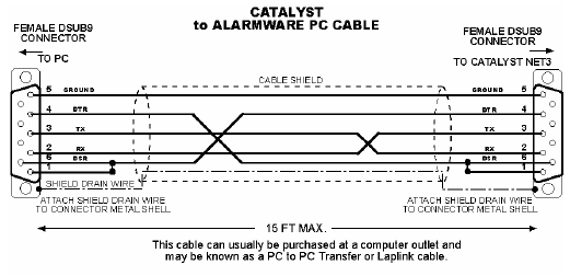
Alarmware and cable are normally supplied with a new Catalyst.
Once connected to the Catalyst via Alarmware we are ready to configure the necessary parameters for communication.
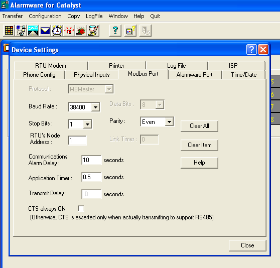
Open Alarmware and go to ‘Devices’ via ‘Configuration’. Once open, click the ‘Modbus Port’ tab. Configure the Modbus parameters beginning with the Baud Rate. Select the speed best suited for your application.
In this case, we have chosen the fastest available at 38.4K baud. The default Stop bits is ‘1’ and Parity should is ‘Even’.
Next, select a Node address for the Catalyst. Default is ‘1’.
Do not check the ‘CTS always ON’ box as we do not require handshaking in this setup.
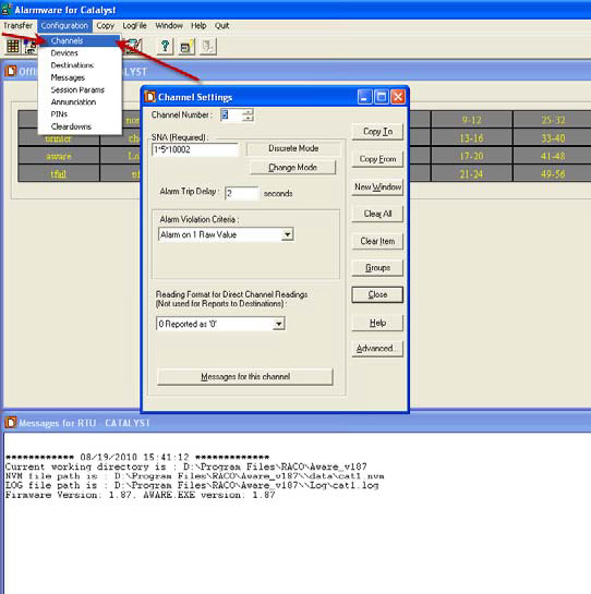
Finally, we will configure the Channel settings. As illustrated on left, go to ‘Channels’ via ‘Configuration’.
The first available data channel to communicate remotely (i.e. virtual, non-hardwired) to a PLC is Channel 5. Once Channel 5 has been selected, we need to identify which data type, within which PLC we want to communicate. This is done via SNA.
Enter the SNA as described below and then follow procedure to complete the Channel settings.
TABLE #1
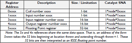
- Important: Register Addresses begin with the number 1 -
Table #1 illustrates the Modbus data file convention within the Catalyst and the link to PLC via the SNA. (Source Net Address)
Important: Although Holding Registers are not currently applicable to Micrologix, it should be noted that Output Register (4xxxx) and Holding Register (5xxxx) data types use the same data area at the Catalyst end.
The Holding Register (5xxxxx) uses two consecutive 16 bit addresses that are interpreted as a 32 bit floating point number. (i.e. 5xxxx & 5xxxx+1)
Not unlike the Holding Register, the Output Register (4xxxx) also reserves two consecutive 16 bit words however the extended word is left blank.
Similarly when addressing the input register (3xxxx), allow for two consecutive 16 bit words, keeping in mind the extended word is reserved but not used.
Hence, consecutive addressing of both Input and Output Registers will appear as follows.
For example, first Input Register address point 30001,2nd address point 30003, 3rd address point 30005, etc.
Constructing the SNA (Source Network Address)
The SNA is comprised of …, Net/Node/Address.
Net: This is either a ‘0’ or ‘1’. ‘0’ when using local physical I/O. ‘1’ when using remote PLC I/O.
Node: This is the node address of the PLC we wish to communicate.
(in this tech note we have configured our Micrologix to have a Node address of ‘5’)
Address: points to the Modbus address mapped to the PLC. (i.e. remote device)
The following two examples construct the SNA for both a discrete an analog PLC point as per file assignment illustrated in this Tech Note.
Example #1: To configure a channel to communicate to B10:0/0, set the SNA as follows.., 1*5*00001
Example #2: To configure a channel to communicate to N21:0, set the SNA as follows.., 1*5*40001
Once channels are configured, they are ready to be assigned to your project typically linked to Alarms and Messages.
For technical support from RACO contact, (510) 658 -6713.