- Make sure Modbus TCP Enable check box is checked as shown.
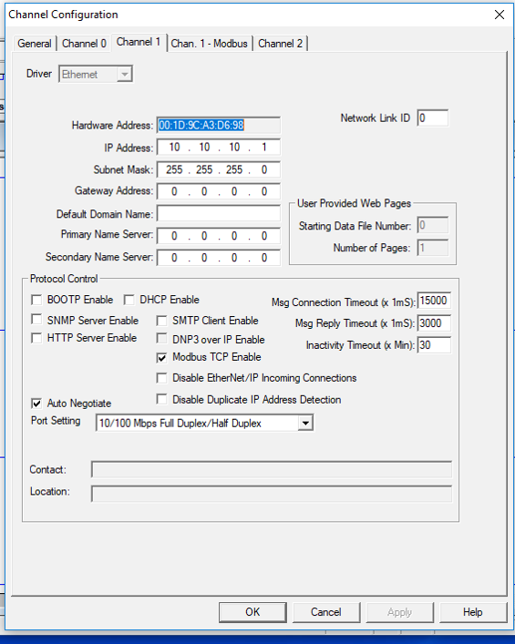
- This screen is for when the Micrologix is the slave device.
- Currently the Micrologix is the master device for communication on the Ethernet with the Catalyst so this screen does not apply.
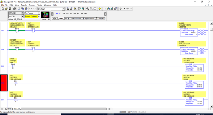
- I chose to stagger my message block execution. That should not be a requirement. T4:48/DN bit closes for one scan every 1 second.
- The B3:44 bits on rung allowed me to do debugging easier by enabling or disabling messages if I wanted to do one at a time.
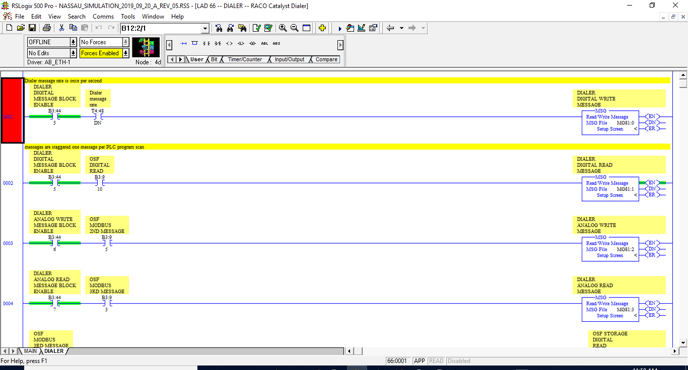
- This image shows how I created the staggering of the messages.
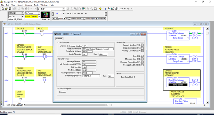
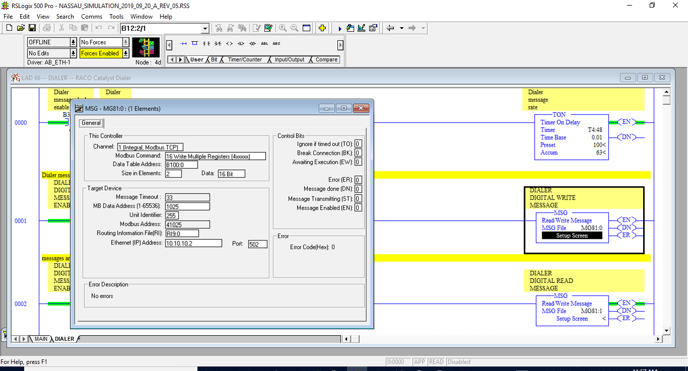
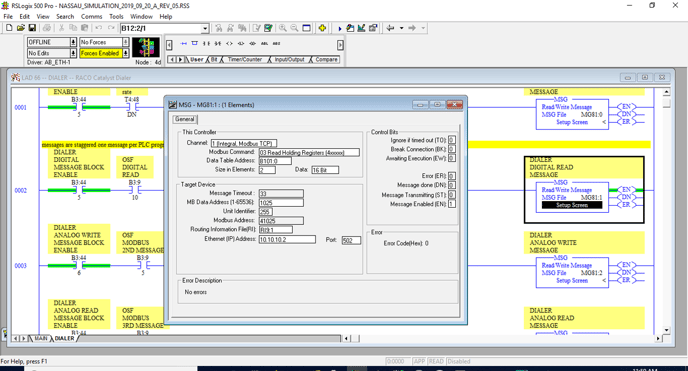
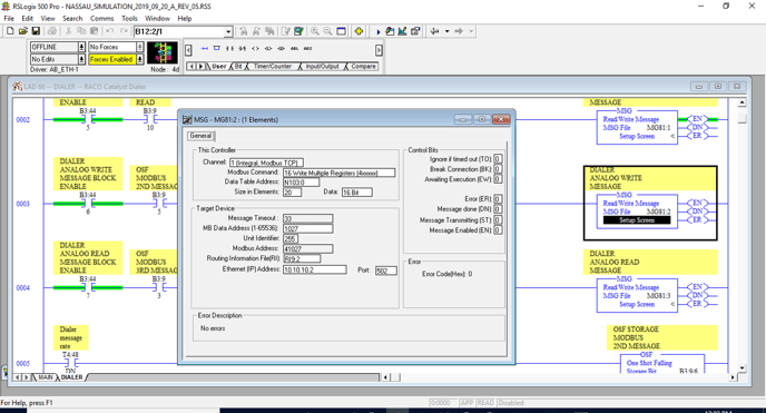
- This is an important screen. Make sure each message instruction has its own unique Routing Information File address assignment.
- Make sure to select the correct option for the Channel as shown.
- Make sure to use correct offset in the Target Device setting for MB Data Address 1025 will put data in the Catalyst memory location 40001
- This is how I chose to send the 32 bits of discrete binary information. I had to flop the bits around in the ladder diagram.
- I had to have my source bit 0 control the destination bit 15. I did this for each bit of the discrete bits transmitted to the Catalyst.
- Note I did not do any bit swapping for the floats or regular integers.
- This is where I send the remaining information to the Catalyst. What is not shown is how I packed the floats into the integer memory.
- This was useful for confirming the transfer of data.
- The reading of the discrete information was solely for the programmer’s convenience.
- This is where I send the remaining information to the Catalyst. What is not shown is how I packed the floats into the integer memory.
- I used a CPY instruction to move one floating point number at a time into a temporary holding of two consecutive integers.
- An example would be CPY from #F8:10 into #N7:70 length 2
- I would then using a branch rung under the CPY instruction place a MOV instructions to copy N7:71 to N103:0 and under that another MOV instruction to copy N7:70 to N103:1
- That is how I packed my floats into the integer space and changed the word order from Little Endian to Big Endian in the MicroLogix 1400.
- I used the same two integer memory locations for all the floating point numbers.
- So the rung under the above described operation would be
- CPY #F8:11 to #N7:70 len 2 and again do the swap but the destination was incremented to the next two integer locations available in the send integer memory in my example N103:2 and N103:3.
- For me I used the last memory location of this 20 memory locations transmitted as a heartbeat. No channel number should be assigned to this memory space.
- My code looks for the number sent to be returned in this read message.
- I compare what was received here against what was sent. If they match, I reset the watchdog timer, and again increment the last memory location of the send message data buffer.