It is important to note that ModbusTCP implementation in all Schneider Electric Controllers is treated the same in all programming products from Schneider Electric (i.e. Concept, ProworxNxt, Proworkx32, UnityPRO). To read and write to a slave device the Schneider Electric controller initiates an MSTR read or write block and indicate the full network address and the register as needed too any ModbusTCP device present on the network. The RACO Autodialer is a slave ModbusTCP device in the Ethernet network (unlike previous implementations over Modbus RTU when the RACO autodialer acted as a Modbus Master
Before you Begin:
Before you get started with the Proworx32 MSTR configuration, it is important to note that this RACO unit is an Ethernet device with an internal Ethernet to Modbus RTU gateway, and as such requires specific address mapping. For example, the MSTR block in Proworx is configured to write its first word from holding register 40406 to the RACO at register 41025 (Input at Func Dependent Info). This 41025 address corresponds to the RACOs internal address of 40001. So if you have a value of 40406= 1234, the output of the MSTR block (41025) would also equal 1234. However, on the RACO side this value would be read at 40001.
MSTR example Configuration in Proworx32:
In this example the MSTR network in Proworx32 is setup such that the MSTR function is only executed once per second (See Ladder logic here). To enter the configuration of the MSTR block, right click on it and select Instruction Editor. We are using this MSTR for Ethernet communications so we need to navigate to page 2 for TCP/IP configuration.
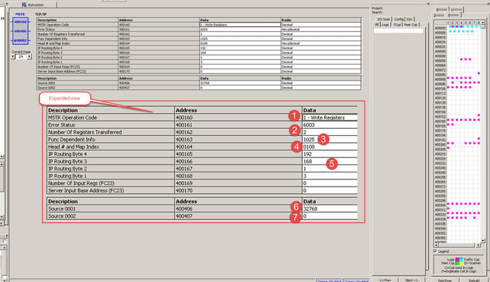
- For MSTR Operation Code select 1 Write Registers.
- We should be writing 2 words to the RACO Autodialer, so the Number of Registers Transferred needs to be 2.
- The Function Dependent Info is the external 4x register we are going to write to. This value must start at 41025 (because the RACO reads this address as 40001 internally), or 1025 as its entered in the data box.
- The Head # and Map Index is where we specify the specific PLC processor being used, as well as the RACOs Modbus address. In our case, the first 2 bits are 01 (for Momentum Processors) and the 3rd and 4th bits are 01 (Our RACOs Modbus Address) respectively.
- The next four IP Routing Bytes are the IP address of the RACO unit, starting with byte 4 as the first 3 digits of the IP address (192.168.1.3).
- Next, the Source 0001 is the first contiguous holding register from which the MSTR block will gather its data to be written to the RACO. This address is entered in the Data Area (Middle Node) of the MSTR block (This is a user specific address -depending on the need of the programmer). The Control Block (Top Node) portion of the MSTR block is the first of 12 holding registers that the function uses, so it is important to verify that you don't overwrite existing 4x registers when setting this address.
- And Finally, the MSTR Length (Bottom Node) is the number of contiguous registers that the MSTR block will be referencing for its write to the RACO.
The configuration of the remote channels in the RACO can be found in the Addendum to Verbatim Gateway Owner’s Manual. One thing to note here is that the RACO interprets register 00001 as bit #1 of holding register 40001.
Example: Remote channel 1 is set for 00001. It will read this bits state from bit #1 of 40001. And 00002 will be read from bit #2 of 40001, etc.