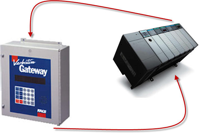
 This technical note explains how to interface the RACO® Verbatim Gateway® system with the Allen-Bradley® SLC™ 5/03, 5/04 and 5/05 family of PLCs having the 9 PIN, male RS232 port. This allows the Verbatim Gateway® to perform its alarm notifications and functions using the existing wiring to Allen-Bradley® SLC™ 500 series as inputs via data communications.
RACO® supplied components:
- Verbatim Gateway® (Any model)
- 510VAB-1 Cable
Allen-Bradley® supplied components:
 SLC 500 Series (SLC 5/03, 5/04, 5/05 family of
PLCs having the 9 PIN, male RS232 port)- (If using SLC™ 5/03 onboard DH 485 port, use the 1747-PIC converter to connect to your PC)
- (If using SLC™ 5/04 onboard DH+™ port, use the PMCK card and 1784-PCM6 cable to connect to your PC)
- (If using SLC™ 5/05 onboard RJ-45 Ethernet port, use a simple CAT 5 cable can be connected to your PC)
- RSLogix™ 500 software version 8.10.00
- RS232 Cable (simple NULL modem – for RSLogix 500 software)
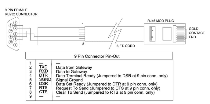
In order to facilitate data communications via DF1 over RS232, RACO provides a simple NULL Modem serial cable, VAB-1 (see above). This cable has the RJ-45 connector required to connect to the Verbatim Gateway. In addition, parameters need to be set within the Allen-Bradley® and RACO Verbatim Gateway.
No additional hardware is required.
Communication Setup for the Allen-Bradley® SLC™ 500 Platform
STEP #1 — Establish the Optimal Method to interconnect between RSLogix™ 500 software and SLC™500 Rather than using DF1 Full Duplex to communicate between the Allen-Bradley® processor and RSLogix™ 500 software, a network communications platform should be considered.
1) To utilize the SLC™ 5/03 onboard DH 485 port, use the 1747-PIC converter to connect to your PC.
2) To utilize the SLC™ 5/04 onboard DH+™ port, use the PMCK card and 1784-PCM6 cable to connect to your PC.
3) To utilize the SLC™ 5/05 onboard RJ-45 Ethernet port, use a simple CAT 5 cable can be connected to your PC.
The DF1 Full Duplex port would then be available to communicate to the Verbatim Gateway.
STEP #2 — Launch RSLogix™ 500 software
Once your RSLogix file is open, you will need to set communications driver to DF1 Full Duplex. Since the Network link typically connects to Chan. 1 – System, the DF1 Full Duplex driver is available at Chan. 0 – System, by default.
STEP #3 — Open the Channel Configuration Form
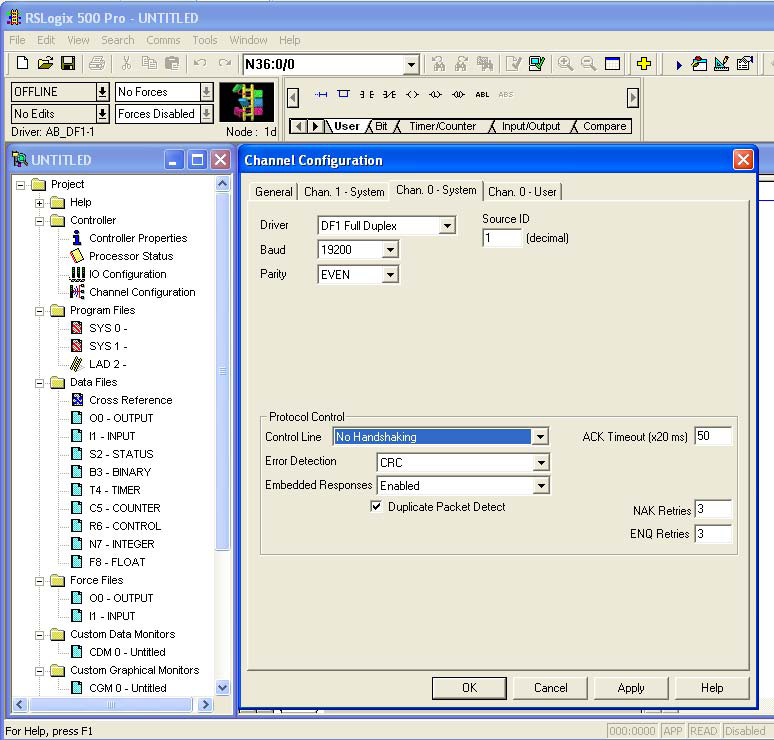 As shown at right, the Channel Configuration form has four tabs: General, Chan. 0 – System, Chan. 1 – System and Chan. 0 – User. Select the Chan. 0 – System tab.
Once the Driver field is clicked, a drop-down menu of driver choices will be visible. Select DF1 Full Duplex, as shown.
STEP #4 Set Communication Parameters
Select DF1 Full Duplex, as shown.
Next, select the Source ID as 1.
RACO recommends the following…
• Baud rate = 19,200
• Parity = EVEN
• Stop Bits =1
• Error Check = CRC
• Control Line = No Handshaking
• Embedded Responses = Enabled / Auto Detect
• NAK Retries = 3
• ENQ Retries = 3
Communication Setup for the Verbatim Gateway
The following seven-step procedure will configure your Verbatim Gateway to link its Remote Channels (RC) to your PLC addresses, via DF1. Once linked, the Verbatim Gateway will monitor RC status and Alarms according to your settings.
Connections to the PLC are via the onboard RJ45 port or NET. With the V232/485, two NET/ports are provided. NET ID = 1 is dedicated to the DH485 protocol and NET ID = 2 is configurable for either Modbus RTU Master or DF1. (Refer to table #1.)
| N | Protocol | Reference | Description | NET |
| 0 | NONE | Device Disabled | All NETs | |
| 2 | DH485 | 7.4.2 | Allen-Bradley DH485 protocol | Net1 on V232/485 only |
| 3 | DF1 | 7.4.1 | Allen-Bradley serial interface | Net1 (on VDP only) Net2 |
| 4 | ||||
| 5 | MODBUSM | 7.4.3 | Modbus Master | Net1 (on VDP only) Net2 |
| 128 | LDL | 7.4.5 | Local Data Logger | Net1 (on VDP only) Net2, 4 |
Table #1
STEP #1 — Protocol Driver (4906)
When setting the Protocol, Node Address and Communication parameters, it is good practice to include the NET ID. (i.e. 4901, 4903, 4904, 4905 and 4906).
Insert the NET ID immediately following the parameter number, as defined below.
As per the Table #1 above, set the Protocol Driver to DF1 on NET 2.
Key in the following… 4906 2 <point> 3 <enter>
To read the Protocol Driver for NET 2, key in the following… 4906 2 <enter>
STEP #2 — Node Address (4905)
Choose a unique DF1 NODE address for the Verbatim Gateway. As illustrated above, we’ve already selected NODE / STATION 1 for the PLC. DF1 allows NODE addresses to range from 1–64.
For example, set the Gateway NODE address to 2 by using code 4905.
To set the NODE address of NET 2, key in the following… 4905 2<point> <2> <enter>
To read the NODE address of NET 2, key in the following… 4905 2 <enter>
STEP #3 — Communication Parameters (4901,4903,4904)
Select the communication parameters. These must match with the driver settings on your PLC.
RACO recommends the following communication settings…
BAUD rate = 19200 for 19200 on NET 1, key in the following.., 4901 2<point>19200 <enter>
Stop Bits = 1 for 1 on NET 2, key in the following… 4903 2<point> 1 <enter>
Parity = EVEN for “EVEN” on NET 2, key in the following… 4904 2<point> 2 <enter>
Parity Definition: 0 = No, 1 = ODD, 2 = EVEN, 3 = SPACE, 4 = MARK
STEP #4 — Confirmations (4900, 4901, 4930, 4946)
Step #4 will validate all preceding steps.
To verify successful network communications on NET 2, key in the following… 4930 <point> 2 <enter>
To read the BAUD rate for NET 2, key in the following.., 4901 2 <enter>
To verify communication settings reflect the above, at NET 2, key in the following… 4900 2<enter>
To verify active node addresses on NET 2, key in the following… 4946 2<enter>
STEP #5 — Set Defaults
This step simplifies Channel Configuration. (i.e. Step 6)
By setting to Default both the NET ID and NODE / STATION address, it is no longer necessary to reference them when setting Channel Configuration.
Set the following to DEFAULT.
1 NET ID, used to communicate via DF1 (i.e. 2)
2 NODE / STATION address of the target PLC
To change the NET ID to 2, key in the following… 4910 2 <enter>
To confirm the NET ID, key in the following… 4910 <enter>
To change the PLC NODE / STATION address to 1 of NET 2, key in the following… 4911 1 <enter>
To confirm PLC NODE / STATION address, key in the following… 4911 <enter>
STEP #6 -- Channel 1 & 2 Configuration (4501) (4502)
Since Verbatim Gateway channels are completely compatible with the logical and I/O addressing scheme for the file structure of the SLC™ series processors, the table below should look familiar.
| Identifier | File Type | Example |
| O | Output | O:1.0/0 (LSV500) O:017/10 (PLC5) |
| I | Input | I:0.1/0 (SLC500) I:013/07 (PLC5) |
| S | Status | S:2 (word) S:2/0 (bit) |
| B | Bit | B:0 (word) B9:0/1 (bit) |
| T | Timer | T4:0.2 (word) T:0.0/1 (bit) |
| C | Counter | C5:0.2 (word) C10:0.0/1 (bit) |
| R | Control | R6:2.1 (word) R:2/15 (bit) |
| N | Integer | N:1 (word) N:1/0 (bit) |
| F | Floating Point | F:2 (32-bit word) |
| NOTE: Cannot specify 16 or 1-bit points with F file type. | ||
| D,G,M1, etc... | All other types | Not Supported |
Table #2
Table #2 shows the Allen-Bradley® supported address types available to link to Verbatim Gateway channels. Indirect, indexed and symbolic addressing schemes are not supported.
The two examples below illustrate the link to the PLC data table (via DF1, Table #2) to the Verbatim Gateway channels.
Example #1
To link B3:0/0 in the PLC to Channel 1 as per the PLC file structure illustrated above, key in the following…
4501 <point> <shift> <B> <3> <shift> <:> <0> <shift> </> <0> <point> <enter>
To verify the current address entered, key in 4501<point><enter>
To read address value, key in 4001<point><enter>, this will read actual PLC value assigned to Channel 1.
Example #2
To link N7:0 in the SLC™ PLC to Channel 2 as per our PLC file structure illustrated above, key in the following… 4502 <point> <shift> <N> <7> <shift> <:> <0> <point> <enter>
To verify the current address entered, key in 4502<point><enter>
To read address value, key in 4002<point><enter>, this will read actual PLC value assigned to Channel 2.
STEP #7 — Assignment of Alarm Conditions
Having created and tested your Remote Channels, Step #6, you are now able to assign alarm conditions.
Channel #1, Configured as Discrete, is either ON or OFF.
Should this channel be linked to a “Failsafe” point in the PLC, (i.e. ON = NORMAL, OFF = ALARM) we
would alarm when OFF. In this case, we would key in … 45 01 2.
To alarm when ON, (i.e. signal is HIGH) key in the following… 45 01 1
To alarm when OFF, (i.e. signal is LOW) key in the following, 45 01 2
To read Alarm status for Channel 1, key in … 4001 <enter>
Channel #2, Configured as Analog, operates within the range from 0 to 65, 535.
Should this channel be linked to a pressure signal in the PLC, and the process requires that pressure
remain within an acceptable level, otherwise ALARM. (For example, BELOW 10,000 AND ABOVE 30,000)
We would key in the following…
To alarm when the analog signal falls below a value, for example 10,000: key in… 45 02 5 10000
To read the LOW set point alarm; key in the following… 45 02 5
To alarm when the analog signal rises above a value, for example 30,000… 45 02 6 30000
To read the HIGH set point alarm; key in the following… 45 02 6
Supporting Integration Notes: SLC™ 500 series PLC via DF1 over RS232