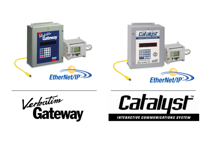
RSLogix 5000 Configuration
for both the
Verbatim Gateway and Catalyst
Autodialer EtherNet Options
Addendum 1.0
Note: It is assumed that the reader of this addendum is already familiar with the basic operation and programming method of the Autodialer product. If this is not the case, please take the time necessary to familiarize yourself with the Autodialer by reading its Owner's Manual. Only the EtherNet-specific features of the Autodialer are described in this addendum.
1.0 Introduction
A) Purpose
The information provided in this document helps the user setup the EtherNet communication between a RSLogix 5000 series PLC and software and a RACO Autodialer with the EtherNet Option. This procedure is for both the Catalyst and Verbatim Gateway Autodialers as the process is the same. We use the general term 'Autodialer' here to refer to both. For brevity, the RSLogix 5000 series PLC and software will be referred to as "RSLogix".
While this is specific to the Rockwell RSLogix 5000 PLCs and software, it offers a general guideline of the required steps for other PLCs.
B) Overview
Configuring RSLogix to connect to an Autodialer is a simple four-step process:
- Add the Autodialer to the RSLogix project (Section 2.1)
- Configure RSLogix for the Autodialer EtherNet Module (Section 2.2)
- Verify the Autodialer Tags (Section 2.3)
- Program RSLogix to trigger an Autodialer alarm channel (Section 2.4)
C) Requirements
|
Description |
Name / Type |
Version |
| Rockwell/Allen-Bradley PLC | RSLogix 5000 series | NA |
| PC connected to the PLC's subnet | Windows PC | NA |
| RACO EDS (Electronic Data Sheet) file | RACO_RTU_V1.0.eds | 1.0 |
| PLC software | RSLogix 5000 | Compatible w/PLC |
| Autodialer Operator's Manual | Autodialer Operator's Manual | 1.87 |
D) Reference Links for Products and Networking
For further information about the Autodialer EtherNet Option products, please consult the RACO Mfg and Eng web pages at www.racoman.com. The latest manuals, software, and the required EDS-files can be downloaded from the online support sections of the web site. These are also included in the CD that is shipped with a new Autodialer.
For more information concerning the EtherNet/IP network the Open EtherNet/IP Vendor Organization has a webpage. Please visit https://www.odva.org for more information about EtherNet/IP.
For more information concerning the Modbus TCP network the Open Modbus Organization has a webpage. Please visit https://www.modbus.org for more information about Modbus TCP.
For information concerning the Allen Bradley PLC's refer to the Rockwell Automation homepage www.rockwellautomation.com
The PLC must be configured in order to connect to the Autodialer.
It is recommended to have a single PLC write to the Autodialer. Although up to 16 connections are possible, they would be writing to the same address(s) and may be cause for unnecessary confusion. We recommend a single write connection however, up to 16 connections may listen/read from the Autodialer.
If your existing network uses more than one controller to provide alarm notification, we would encourage messaging all alarms to a single controller (data concentrator) that would, in turn, connect to the Autodialer.
A) Adding the Autodialer EtherNet Module to the RSLogix Project
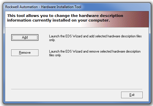
The RSLogix project must be configured with the proper setting to communicate with the Autodialer EtherNet Module. An Electronic Data Sheet (EDS) file that contains this information needs to be installed onto your system via the EDS Hardware Installation Tool.
a. Adding the Autodialer EtherNet Module to RSLogix
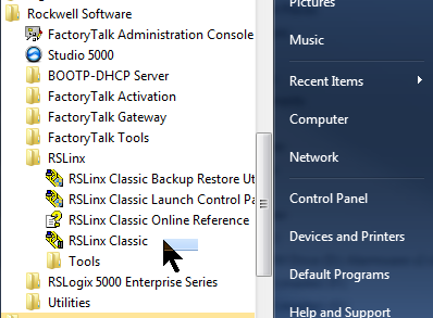
1. Click Start > All Programs > Rockwell Software > RSLinx > Tools > EDS Hardware Installation Tool.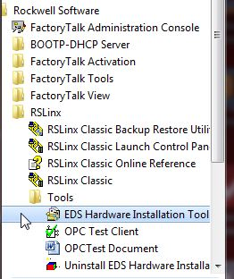
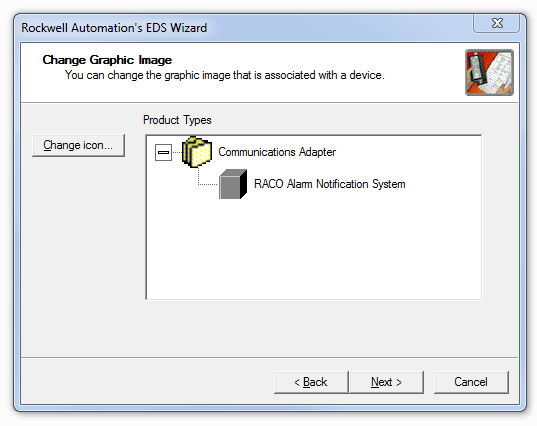
2. Click Add to launch the EDS Wizard and follow the steps.
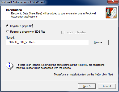
3. Select Register a single file then browse to the location of the Autodialer EDS file. The EDS file is located in the "program files\RACO\IPConfig Tool" folder of the CD that came with the Autodialer.
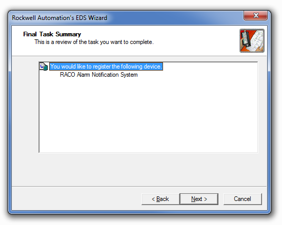
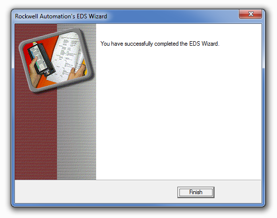
4. Click Next at the following windows then Finish and Exit the Wizard.
b. Verify EtherNet connectivity between the PC, PLC, and Autodialer
1. Click Start > All Programs > Rockwell Software > RSLinx Classic
2. Select the Communications menu and then chose RSWho.
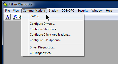
3. Expand the AB_ETHIP-1 branch and you should be able to see the Autodialer IP and the PLC IP.

B) Configuring the RSLogix for the Autodialer EtherNet Module
The RSLogix must be configured to properly work with the Autodialer EtherNet Module
a. Add the Autodialer EtherNet Module to the RSLogix project.
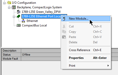
1. Start RSLogix and either start a new project or open an existing project. Refer to the Rockwell documentation for this procedure. For this example we will use Green_Valley_DPW
2. In the RSLogix Controller Organizer, expand the I/O Configuration until you can see the EtherNet adapter. Right-Click on the EtherNet adapter and choose New Module
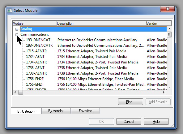
3. Expand the Communications branch, then scroll down and select the Generic EtherNet Module. This generic module will be configured to match the Autodialer module.
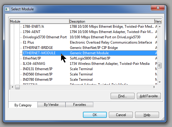
4. Click OK to close the window and the New Module window will open.
5. Enter the values as shown here. For Name you can use whatever you like. Whatever name you enter here will be used as the name for the tags that will be assigned to the Autodialer. Enter the actual IP address of your Autodialer.
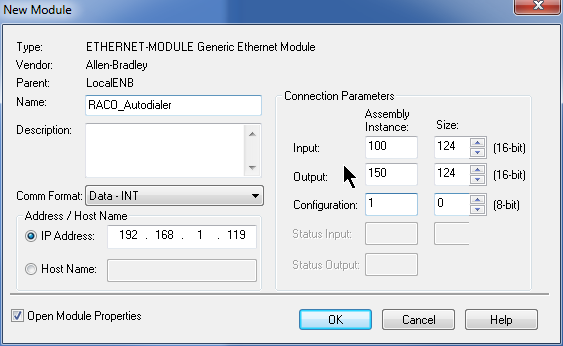
Comm Format sets the size and type of the data registers. Data - INT is 16-bit integer registers.
Assembly Instance tells the PLC where to access the Autodialer's data. These must be set as shown. Size identifies how many registers the Autodialer can adress
The Autodialer does not use a Configuration register but RSLogix requires a value greater than zero be entered here.
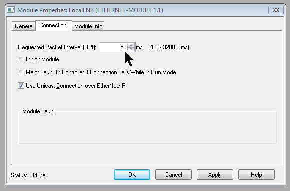
6. Click OK after entering the values. The Module Properties window will open. Click the Connection tab and enter 50 for the Requested Packet Interval. Since the alarm system doesn't require a fast response, we can increase the scan time interval to reduce network traffic. Leave the other setting as shown.
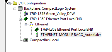
7. The Autodialer has been added to the I/O configuration in RSLogix5000. The controller organizer I/O Configuration should be similar to this. The name that you entered for the module would appear in place of RACO_Autodialer.
C) Verify the Autodialer Tags
The tags are created when the Autodialer EtherNet Module is added. Verify that they were successfully added to the tag library.
a. Display the Tags
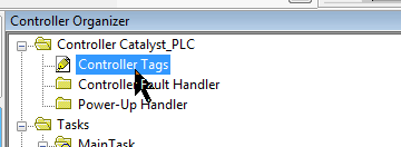
1. Open the Controller Tags window
2. Click on the Monitor Tags tab at the bottom of the window if it is not already selected.You should be able to see the three tag groups that correspond to the EtherNet Module that you just added, RACO_Autodialer in this example. There are a set of input tags (I), output tags (O) and configuration tags (C). The C tags may not show up in some software versions as they aren't used.
3. Expand the RACO_Autodialer:O.Data tag group. RSLogix has created 124 registers (0 to 123) as we defined in the EtherNet Module setup. Each of these data type tags correspond to a SNA Analog register in the Autodialer:|
|
RSLogix Register |
Autodialer Analog Register |
|
RACO_Autodialer:O.Data[0] |
SNA 1*2*40001 |
|
RACO_Autodialer:O.Data[1] |
SNA 1*2*40002 |
|
... |
... |
|
RACO_Autodialer:O.Data[123] |
SNA 1*2*40124 |

Click to expand
4. Fully expand the RACO_Autodialer:O.Data[0] tag.You can see that RACO_Autodialer:O.Data[0] contains 16 tags which correspond to 16 discrete bits in the RACO_Autodialer:O.Data[0] register. Each of these tags corresponds to a SNA Discrete register bit in the Autodialer.
|
RSLogix Bit |
Autodialer Discrete Register |
|
RACO_Autodialer:O.Data[0].0 |
SNA 1*2*00001 |
|
RACO_Autodialer:O.Data[0].1 |
SNA 1*2*00002 |
|
... |
... |
|
RACO_Autodialer:O.Data[123].15 |
SNA 1*2*01984 |
It's obvious from this view that the RACO_Autodialer:O.Data[0] register occupies the same memory space as the discreet bits RACO_Autodialer:O.Data[0].0 to RACO_Autodialer:O.Data[0].15 . Similarly, Analog register SNA 1*2*40001 occupies the same memory space as the 16 discrete SNAs 1*2*00001 to 1*2*00016. Refer to the Autodialer's EtherNet Addendum for more details on the address mapping scheme.
Catalyst: Section II.C. Catalyst Data Register SNA Addressing
Verbatim Gateway: Section II.C. Gateway Data Register SNA Addressing

5. When the PLC is Online, this window can be used to monitor and force the tags. The Value column shows the current value of the register. A value can be manually entered in the Value column to force the register to that value. Forcing a value for a 16 bit register (e.g. RACO_Autodialer:O.Data[0] ) will force all of the 16 bits that it contains. (RACO_Autodialer:O.Data[0].0 to .15)
D) Program RSLogix to trigger an Autodialer alarm channel
Programming the PLC logic is the user's responsibility and will not be covered in detail here. These are a couple of simple example of how to trigger an Autodialer alarm channel. You must also configure the Autodialer to assign the SNA that corresponds to that tag to an alarm channel. Refer to the Autodialer's EtherNet Addendum: Section D. Assigning an SNA to a Channel for more details.
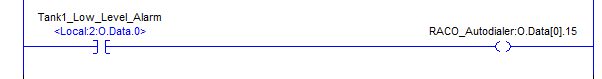
a. Ladder Logic Example using Coils
1. The simplest way is to add a coil and then use the Tag Browser to assign the coil to the desired Autodialer tag, RACO_Autodialer:O.Data[0].15 as in this example:
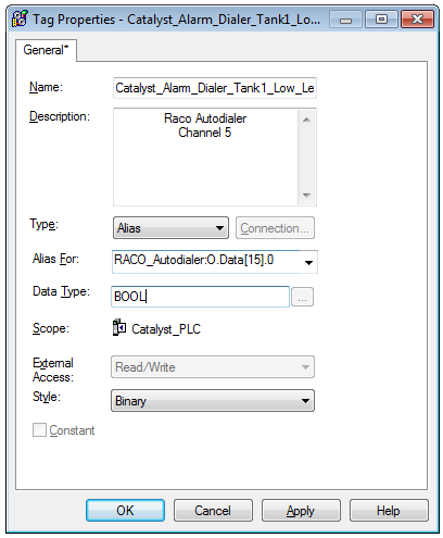
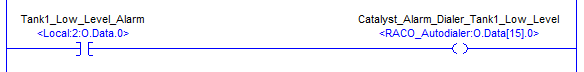
b. Ladder Logic Example using Alias Tags
1. You could also add an alias for the desired alarm and assign it to the RACO_Autodialer tag that you wish to use:
2. Add a rung that sets that alias coil when the desired alarm condition is met:
Once the configuration and programming is complete you may go Online and download and test the program. Please refer to the Rockwell documentation and resources for assistance with the general procedures for programming and testing your PLC.